I am working on a steel trough girder bridge. Due to its relatively small size (not possible to inspect by a person inside), there is a requirement that the girder needs to be fully airtight and confirmed by pressure testing.
Apart from that, there are no guidelines that I am aware of, so I wonder if anyone has previous experience?
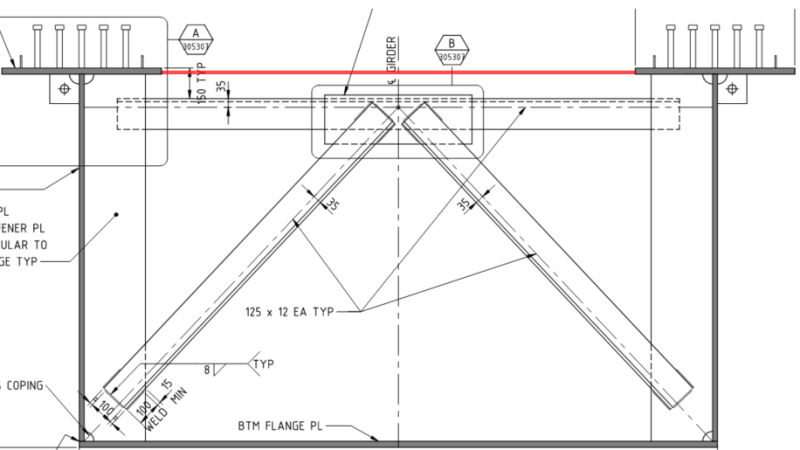
Figure below is showing the typical cross-section with proposed seal plate shown in red. Thickness would be maybe 5 or 6 mm. The seal plate has not been considered in the capacity of the girder so slenderness is no issue, although I need to confirm that the thickness is OK for the pressure test. The seal plate will rest on the diagonal bracing so it is not suspended in air as it would appear in this below cross section.
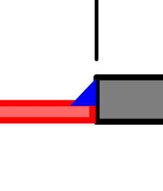
For the weld along the edges of the seal plate, I would imagine some small fillet weld as shown below is likely. Due to the fact that our code does not allow a single-sided fillet weld to carry a bending moment, I would need to treat the edges as though they were pinned. But I don't think this will be an issue.
In terms of pressure testing, this is where I am a bit stuck. The fabricator will need to install a valve and pressurize the girder. I am leaning towards adopting a similar approach for PT ducts - something like 2x atmospheric pressure with no notable drop in pressure after 1 minute.
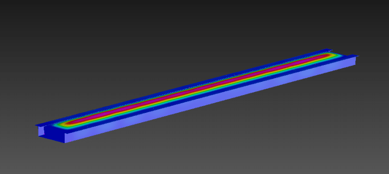
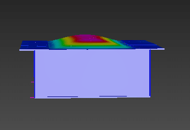
My final concern is the performance of the weld when the beam is eventually loaded. No doubt the seal plate will want to buckle (which is OK as we are not relying on its strength), but would this buckling cause any unforeseen loads on the welds that would cause them to fail?
Apart from that, there are no guidelines that I am aware of, so I wonder if anyone has previous experience?
Figure below is showing the typical cross-section with proposed seal plate shown in red. Thickness would be maybe 5 or 6 mm. The seal plate has not been considered in the capacity of the girder so slenderness is no issue, although I need to confirm that the thickness is OK for the pressure test. The seal plate will rest on the diagonal bracing so it is not suspended in air as it would appear in this below cross section.
For the weld along the edges of the seal plate, I would imagine some small fillet weld as shown below is likely. Due to the fact that our code does not allow a single-sided fillet weld to carry a bending moment, I would need to treat the edges as though they were pinned. But I don't think this will be an issue.
In terms of pressure testing, this is where I am a bit stuck. The fabricator will need to install a valve and pressurize the girder. I am leaning towards adopting a similar approach for PT ducts - something like 2x atmospheric pressure with no notable drop in pressure after 1 minute.
My final concern is the performance of the weld when the beam is eventually loaded. No doubt the seal plate will want to buckle (which is OK as we are not relying on its strength), but would this buckling cause any unforeseen loads on the welds that would cause them to fail?