Continue to Site

Eng-Tips is the largest engineering community on the Internet

Intelligent Work Forums for Engineering Professionals

  • Congratulations IDS on being selected by the Eng-Tips community for having the most helpful posts in the forums last week. Way to Go!

Secondary Reformer Return Line Weld Failure 1

Status
Not open for further replies.

sahsanb

Materials
May 31, 2013
56
Dear All,

We recently observed leakage from welding joint of our Secondary Reformer return line. Mentioned below are brief details of piping:

Service: Process Air
Operating Temp= 550-560 C
Operating pressure= 36 kg/cm2 g
Pipe Material: ASTM A 312 TP321 H
Radiography: 100 % at time of commissioning
Service Life: 3-4 years ( Seen multiple startups due to gas curtailment issues)
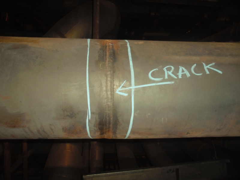
DSC01090_bifq7d.jpg


Apologies for not being able to share additional information other than crack's actual picture as since the line was at very high temperatures during weld repairs we could not perform any NDEs.

Request your expert opinion on below mentioned points:

- Possible damage mechanisms for an in-service defect considering piping metallurgy and operating conditions
- Impact of welding practices that could have resulted in issues in weld joint microstructure, which aggravated in years to come resulting in a crack. Any special precautions that should be undertaken for welding SS 321 H in high temperature service?
- Impact of multiple startups, possibly causing fatigue failure due to cyclic stresses. Please note their is an elbow downstream of the weld joint and its weld joint was found to be in satisfactory condition during visual inspection
- Recommended inspections for next available opportunity

Regards,
Ahsan
 
Replies continue below

Recommended for you

Is the crack following the toe of the butt weld in the picture above? How is this line supported?
 
Yes the crack is following the toe of butt weld. Attached is a better picture of crack for your review.

The is line is supported with fixed spring supports. No significant vibrations have been reported on this line in the past.


 http://files.engineering.com/getfile.aspx?folder=9509fe9d-3e47-4296-a5b0-68553f4701f0&file=DSC01094.JPG
This is probably a thermal/mechanical fatigue crack initiating from the OD and propagating toward the ID (just a guess). Regarding weld repair, you remove the entire crack, verify removal using NDT, and weld the excavation with the recommended filler metal and minimize heat input. Perform a final NDT.

The key is to determine the source of the bending stresses leading to fatigue crack initiation and propagation. I would re-inspect this weld on a regular basis and review operating process conditions.
 
Hi Sahsanb,

In addition to the advises of metengr it may be of benefits to consider the following points:-

-What was the welding metallurgy at the time of fabrication? and after 4 years of service @ 550-560 C. Typically 321H and 347H alloys have a tendency to develop some sigma phase after prolonged exposure to the above temperature range.
-As we all know welds staring ferrite typically 8 FN or above have a tendency of converting to sigma phase upon prolonged exposure and sigma reduces ductility including the Creep Ductilty.
-321H and 347H piping in thick sections (3/4" and above) could undergo Stress Relaxation or reheat Cracking in service.There had been ample evidences of this in the industry.
-If you're talking about a secondary reformer( I'm assuming for Fertilizer Plant) this unit is of tremendous importance to the plant.Hence any Hit and Miss Assessment would not be advisable.

I'm not sure about your location , however if you call a good lab for In-Situ metallurgy and then manage to cut a BOAT-SAMPLE for Lab analysis, you'll have a through picture of the root causes of the failure and effective mitigation plan, in future.

Pradip Goswami,P.Eng.IWE
Welding & Metallurgical Specialist
Ontario,Canada.
ca.linkedin.com/pub/pradip-goswami/5/985/299
All provided answer are personal opinions or personal judgements only. It's not connected with any employers by any means.
 
the origin could be clarified by studying the crack nature and propagation.
you could perform metallographic cross sections and take pictures of the opened crack.
 
The metallurgy of these alloys makes repairs after extended service more complicated. You need a thorough evaluation on that aspect.
I second the comments that this looks to be driven by thermal induced bending stress. You should re-evaluate the pipe supports and thermal expansion conditions.
And inspect these welds regularly! This one and others in this same run.

= = = = = = = = = = = = = = = = = = = =
P.E. Metallurgy, Plymouth Tube
 
I think you do need to look at metallurgical structure through the weld and HAZ even if it confirms the issue is totally mechanical. It would be ideal if you could remove this joint from service to allow complete examination as outlined above. If this is not an option, then you could collect a boat sample across the weld and HAZ at the center of the crack prior to weld repair. This would allow microhardness measurements as well as direct observation of weld and HAZ structure below the structure. The 3rd (and least favorite) metallurgical option would be to collect a replica on the surface prior to repair at the center of the crack, but this would only provide you with surface structure.
 
In addition to mrfailure. Proper solution annealing temp is paramount to this alloy's success at these operating conditions. In the late '60s and early '70s a number of such HAZ cracking incidents were reported and linked to solution annealing at the temperature commonly used for type 304.
 
Status
Not open for further replies.

Part and Inventory Search

Sponsor