Continue to Site

Eng-Tips is the largest engineering community on the Internet

Intelligent Work Forums for Engineering Professionals

  • Congratulations The Obturator on being selected by the Eng-Tips community for having the most helpful posts in the forums last week. Way to Go!

Seeking Guidance for My First GD&T Application on a Bracket Assembly

MPSU

Automotive
Aug 26, 2024
16
Hey everyone,

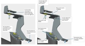
I'm a bit of a novice when it comes to GD&T. I can read drawings and figure out how to design a checking gauge based on the GD&T, but this is my first time being tasked with applying GD&T to a part. My boss has handed me a bracket that attaches to a car and supports the spoiler, and I'm looking for some advice.

I've attached a picture showing how the bracket assembles onto the car, along with my initial thoughts on the GD&T. Specifically, I'm looking for feedback on:

  1. Does my Datum scheme make sense for this part and its function?
  2. Does my approach to checking the part seem practical?
I’d really appreciate any insights or suggestions from those with more experience. Thanks in advance for your help!

Looking forward to your thoughts!Bracket.jpg
 
Replies continue below

Recommended for you

If datum feature A is a plane then datum feature B can only have a perpendicularity tolerance control applied, not a position tolerance control, to orient it to datum feature A.

While it overall does meet the selection of datum features as functional, the control those features have on installing the part seem soft; that the part can get a lot of wiggling to get it to fit in the next assembly and most of the rigidity in the location of those features in the next assembly depend on the mating parts. Not terrible, just not great; in the middle.

If it were mine, I would use the large flat face as a basis for a datum feature - being formed sheet metal I would use 3 datum targets on the face for a primary datum feature. Then select two points, widely separated along the perimeter as a secondary datum feature, and finally a third target point such that translation along the secondary datum feature is well arrested.

This would allow a rigid fixation of the part and leave all the contacting surfaces available for inspection in a single datum reference frame.

While this would introduce an extra path in the tolerance loop, it means that the part can be slammed into an inspection fixture on the line and checked reliably in seconds. If there is some unwanted variation, it will not add up. For example, if the original surface chosen for the datum feature A gets a tiny extra twist when it is formed then datum feature C will appear to be far out of position when no other error in the forming process has occurred. In the use of target points right away it can be detected that only that surface is out of the expected alignment. Since the large flat surface and its perimeter is made before all other features and that perimeter is inspected at that time, it will be unaffected by the downstream operations.

As a design problem, I would add a close tolerance hole in the large flat surface and a close tolerance on a slot in that same surface so that tapered pins could be used instead of the perimeter; these features would locate the part during the subsequent forming operations.
 
Datum feature A is too small to be used as a primary datum. You will need to use datum feature A - C.

Best regards,

Alex
 
Last edited:
If datum feature A is a plane then datum feature B can only have a perpendicularity tolerance control applied, not a position tolerance control, to orient it to datum feature A.

While it overall does meet the selection of datum features as functional, the control those features have on installing the part seem soft; that the part can get a lot of wiggling to get it to fit in the next assembly and most of the rigidity in the location of those features in the next assembly depend on the mating parts. Not terrible, just not great; in the middle.

If it were mine, I would use the large flat face as a basis for a datum feature - being formed sheet metal I would use 3 datum targets on the face for a primary datum feature. Then select two points, widely separated along the perimeter as a secondary datum feature, and finally a third target point such that translation along the secondary datum feature is well arrested.

This would allow a rigid fixation of the part and leave all the contacting surfaces available for inspection in a single datum reference frame.

While this would introduce an extra path in the tolerance loop, it means that the part can be slammed into an inspection fixture on the line and checked reliably in seconds. If there is some unwanted variation, it will not add up. For example, if the original surface chosen for the datum feature A gets a tiny extra twist when it is formed then datum feature C will appear to be far out of position when no other error in the forming process has occurred. In the use of target points right away it can be detected that only that surface is out of the expected alignment. Since the large flat surface and its perimeter is made before all other features and that perimeter is inspected at that time, it will be unaffected by the downstream operations.

As a design problem, I would add a close tolerance hole in the large flat surface and a close tolerance on a slot in that same surface so that tapered pins could be used instead of the perimeter; these features would locate the part during the subsequent forming operations.
Interesting insights! A few points for clarification:

  1. When you suggest using the largest surface as the primary datum and defining the secondary datum along the perimeter, wouldn’t trimming variations potentially affect the hole positions?
  2. Since adding an extra hole in the large surface isn’t an option, how would you adapt your recommendation?
  3. What controls would you suggest for the other surfaces—should we use surface profile tolerances? And should positional tolerances be applied to all the holes?
 
Hi, MPSU:

What you need for this like this is "Planar Common Datum Features". Please take a look at Figure 7-27, ASME Y14.5-2018.

Best regards,

Alex
 

Part and Inventory Search

Sponsor