Hi all,
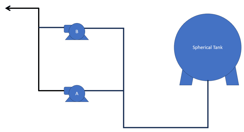
We have this problematic multistage vertical centrifugal pump that seizes every time it is shut down. We’ll call this problematic pump as Pump B because it is a standby unit to another pump that we’ll call Pump A. See pump operating info below:
Service Liquid: Propylene
Density: 480 kg/m3
Flow rate: 34 m3/hr
Suction Pressure: 12 bars
Discharge Pressure 54 bars
Suction Temperature: 30 degC
Once Pump B started up it will run continuously without much issues. Parameters seem normal and vibrations are low. It is only when it is shut down does its shaft seizes at some point during coast down. The point of seizure is usually between the balancing drum and its balancing drum liner. Here are some photos:
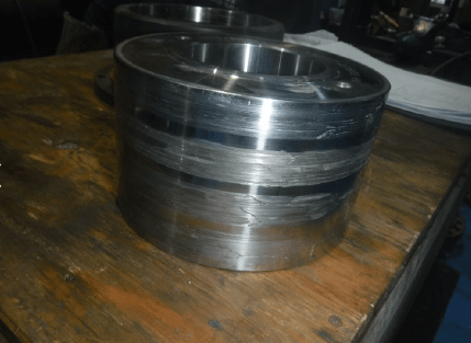
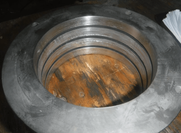
I have also included the drawing of the pump. The balancing drum and balancing drum liner is on Pos. 603.01 and 605.01 respectively.
I had the clearance between the balancing drum and its liner measured thinking that the clearance between them could be the issue. As found clearance was 0.28mm and as per equipment manual the maximum allowable clearance is 0.285mm. I recommended the balancing drum and liner be replaced because the clearance is close to the maximum allowance. The brand new balance drum and liner clearance was 0.17mm.
Then I had the runout of the shaft measured. As found the highest runout measured was at 0.076mm close to the mechanical seal area. This was beyond the acceptable runout of 0.025mm so I recommended to have the shaft replaced. Unfortunately, the only available spare shaft had a runout of 0.038mm also close to the mechanical seal area. There was no choice at the time so the spare shaft with the lower runout was installed despite exceeding the allowable tolerance. Pump was reinstated and it was able to run for a total of 54 days without any issues. Operation had to be stopped because we had a schedule shutdown for the plant. The pump did not seize this time. When it was time to operate Pump B, we observed that the balancing drum pressure and the discharge pressure of Pump B was fluctuating. The operators decided to switch the operating pump to Pump A. Pump B did not seize this time upon turn off. After 5 days of Pump A operating, our maintenance scheduled a test run of Pump B to observe its performance. During the testing, the balancing drum pressure and the discharge pressure was fluctuating again and the testing was discontinued after a few minutes I think. After shutting it off, the shaft seized during its coast down and the pump was pulled out for overhauling. The seizure point was between the balancing drum and the balancing drum liner again. Maintenance did not replace them this time but instead polished the surface to remove the scratches. Clearance between the two are still within tolerance after polishing. We checked the runout of the shaft as well and it seems to have changed from the previous measurement. Now it has a runout of 0.07mm at the coupling area and 0.05mm at the balancing drum area which both exceed the 0.025mm tolerance. Still no spare shaft available for replacement. We were against installing the shaft because of this but our Maintenance and Operations department agreed to install it anyway and see if the pump will run despite the shaft condition. It was put into service and surprisingly, it was able to run without any issues. It was agreed upon that Pump B will be put continuously in service until the new spare shaft arrive. 8 days later, we had a process upset in a different area which required a plant shutdown, hence, also requiring the pump to be shut down. And the shaft seized during coast down.
I have a few suspects on what could be causing the issue:
A. Excessive shaft runout – this seems like the most obvious reason. However, I am thinking that the excessive shaft runout may also be the aftereffect of the seizure due to the impact/momentum of the sudden stop of rotation. And it’s also puzzling why the seizure only occurs after shutting down the pump, when the shaft is coasting down and does not happen during startup. I expect if the excessive runout was the root cause, then shouldn’t the pump seize upon startup? I am not sure.
B. Pump was not properly vented/primed – this could explain the case when we had to discontinue the pump testing due to the fluctuations in the discharge and balance drum pressure as it was only a few minutes between pump startup and shut down. But I don’t think this could explain the pump seizure where the pump ran for days without any issues.
C. Foreign bodies get stuck between the balancing drum and balancing drum liner – I also considered this but again, how come it only seizes after when it is shut down? It’s kind of unlikely that no foreign body enters the pump during days of operation and only when it is shut down do foreign bodies enter to cause seizure. And also why is Pump A not affected given that their suction line is common.
Currently the new spare shaft has arrived. We’ve checked the runout and the max runout we measured was 0.015mm which is acceptable. Another concern is will the seizure stop from occurring once we replace the shaft. If the excessive runout is not the root cause and only an aftereffect of the seizure, then this new shaft would also have excessive runout if the seizure still occurs.
What do you guys think? Any inputs would be appreciated.
We have this problematic multistage vertical centrifugal pump that seizes every time it is shut down. We’ll call this problematic pump as Pump B because it is a standby unit to another pump that we’ll call Pump A. See pump operating info below:
Service Liquid: Propylene
Density: 480 kg/m3
Flow rate: 34 m3/hr
Suction Pressure: 12 bars
Discharge Pressure 54 bars
Suction Temperature: 30 degC
Once Pump B started up it will run continuously without much issues. Parameters seem normal and vibrations are low. It is only when it is shut down does its shaft seizes at some point during coast down. The point of seizure is usually between the balancing drum and its balancing drum liner. Here are some photos:
I have also included the drawing of the pump. The balancing drum and balancing drum liner is on Pos. 603.01 and 605.01 respectively.
I had the clearance between the balancing drum and its liner measured thinking that the clearance between them could be the issue. As found clearance was 0.28mm and as per equipment manual the maximum allowable clearance is 0.285mm. I recommended the balancing drum and liner be replaced because the clearance is close to the maximum allowance. The brand new balance drum and liner clearance was 0.17mm.
Then I had the runout of the shaft measured. As found the highest runout measured was at 0.076mm close to the mechanical seal area. This was beyond the acceptable runout of 0.025mm so I recommended to have the shaft replaced. Unfortunately, the only available spare shaft had a runout of 0.038mm also close to the mechanical seal area. There was no choice at the time so the spare shaft with the lower runout was installed despite exceeding the allowable tolerance. Pump was reinstated and it was able to run for a total of 54 days without any issues. Operation had to be stopped because we had a schedule shutdown for the plant. The pump did not seize this time. When it was time to operate Pump B, we observed that the balancing drum pressure and the discharge pressure of Pump B was fluctuating. The operators decided to switch the operating pump to Pump A. Pump B did not seize this time upon turn off. After 5 days of Pump A operating, our maintenance scheduled a test run of Pump B to observe its performance. During the testing, the balancing drum pressure and the discharge pressure was fluctuating again and the testing was discontinued after a few minutes I think. After shutting it off, the shaft seized during its coast down and the pump was pulled out for overhauling. The seizure point was between the balancing drum and the balancing drum liner again. Maintenance did not replace them this time but instead polished the surface to remove the scratches. Clearance between the two are still within tolerance after polishing. We checked the runout of the shaft as well and it seems to have changed from the previous measurement. Now it has a runout of 0.07mm at the coupling area and 0.05mm at the balancing drum area which both exceed the 0.025mm tolerance. Still no spare shaft available for replacement. We were against installing the shaft because of this but our Maintenance and Operations department agreed to install it anyway and see if the pump will run despite the shaft condition. It was put into service and surprisingly, it was able to run without any issues. It was agreed upon that Pump B will be put continuously in service until the new spare shaft arrive. 8 days later, we had a process upset in a different area which required a plant shutdown, hence, also requiring the pump to be shut down. And the shaft seized during coast down.
I have a few suspects on what could be causing the issue:
A. Excessive shaft runout – this seems like the most obvious reason. However, I am thinking that the excessive shaft runout may also be the aftereffect of the seizure due to the impact/momentum of the sudden stop of rotation. And it’s also puzzling why the seizure only occurs after shutting down the pump, when the shaft is coasting down and does not happen during startup. I expect if the excessive runout was the root cause, then shouldn’t the pump seize upon startup? I am not sure.
B. Pump was not properly vented/primed – this could explain the case when we had to discontinue the pump testing due to the fluctuations in the discharge and balance drum pressure as it was only a few minutes between pump startup and shut down. But I don’t think this could explain the pump seizure where the pump ran for days without any issues.
C. Foreign bodies get stuck between the balancing drum and balancing drum liner – I also considered this but again, how come it only seizes after when it is shut down? It’s kind of unlikely that no foreign body enters the pump during days of operation and only when it is shut down do foreign bodies enter to cause seizure. And also why is Pump A not affected given that their suction line is common.
Currently the new spare shaft has arrived. We’ve checked the runout and the max runout we measured was 0.015mm which is acceptable. Another concern is will the seizure stop from occurring once we replace the shaft. If the excessive runout is not the root cause and only an aftereffect of the seizure, then this new shaft would also have excessive runout if the seizure still occurs.
What do you guys think? Any inputs would be appreciated.