Continue to Site

Eng-Tips is the largest engineering community on the Internet

Intelligent Work Forums for Engineering Professionals

  • Congratulations IDS on being selected by the Eng-Tips community for having the most helpful posts in the forums last week. Way to Go!

Selection of Transformer to Supply a Cyclic Load 2

Status
Not open for further replies.

VTer

Electrical
Dec 23, 2008
240
Hi All,

I saw a reference that "When the load cycle is sufficiently short so that the temperature of the transformer does not change appreciably during the
cycle, the minimum transformer size is the rms value of the load."

The equation that is provided is S=sqrt((S1^2*t1+S2^2*t2)/t(cycle))

For example: S1=100kVA for 2 min, S2=50kVA for 2min total cycle time is 4 min.

Using the above equation the resultant min transformer size is 79kVA.

My question is, why the need to perform RMS of the load which is already a resultant value of RMS current and voltage? Why not just take the average value which in this case would be 75kVA?


"Throughout space there is energy. Is this energy static or kinetic! If static our hopes are in vain; if kinetic ù and this we know it is, for certain ù then it is a mere question of time when men will succeed in attaching their machinery to the very wheelwork of nature". û Nikola Tesla
 
Replies continue below

Recommended for you

That would come back to the difference between average and RMS.
If the heating was linear with the current then average or mean would be appropriate.
However the heating is proportional to the square of the current, hence the Root Mean of the Squares.
Still to be considered is the transformer regulation, and possible code requirements for transformer loading.

Bill
--------------------
"Why not the best?"
Jimmy Carter
 
Hi Waross,

Yes, thank you for clearing that up. I didn't consider the i2R relationship and was looking at it from the energy or average power throughput point of view, not the heating effect. Thanks again!

"Throughout space there is energy. Is this energy static or kinetic! If static our hopes are in vain; if kinetic ù and this we know it is, for certain ù then it is a mere question of time when men will succeed in attaching their machinery to the very wheelwork of nature". û Nikola Tesla
 
For cyclic/pulsating loads, err on the side of caution and size the trafo conservatively; some may whine about the additional capital cost for a while, but you'll never hear the end of it if the bank cooks prematurely and there's a major production loss.

CR

"As iron sharpens iron, so one person sharpens another." [Proverbs 27:17, NIV]
 
I hear you CR
How many times has a customer sworn emphatically that conditions will never change.
Then he blissfully changes the conditions and cries when a component that was never meant for those conditions fails.

Bill
--------------------
"Why not the best?"
Jimmy Carter
 
See IEEE 57.96 Table 5—Daily loads above rating to give normal life expectancy in 30°C average ambient for transformers with a 30 min time constant
3.4 Loading on the basis of short-time loads.
 
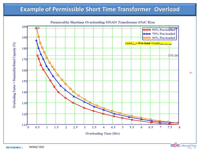
Below is an example of permissible short time transformer overload for various pre-loading scenarios.

Hope this helps.

Short_Time_Transformer_Overload_sqyh8k.jpg
 
I suggest that the total cycle time and the RMS loading should fall below the curves that Cuky2000 just posted.

Bill
--------------------
"Why not the best?"
Jimmy Carter
 
There is another aspect to be considered when transformers are supplying cyclic load.
That is bracing of transformer windings.
When transformer windings receive a shock load hour after hour for days and weeks, the winding braces get loosened in course of time, leading to a fault in the transformer.
It is important to have a discussion with transformer designer as to the additional strengthening of the bracing during manufacture.
 
Valid point, RRaghunath; that being said, not all cyclic loads are shock or step loads, either...

CR

"As iron sharpens iron, so one person sharpens another." [Proverbs 27:17, NIV]
 
Hi All,

Thank you for the feedback, this is a great discussion. My initial questions was regarding shorter duration cyclic loads in terms of cycles and seconds, not so much longer term overload conditions. For example, 50kVA at 450ms then 200kVA at 50ms and so on.

The comment on "additional" bracing is interesting. How would one take that into consideration for standard off-the-shelf transformers? How is that different or similar from processes that include DOL motor starting that although not as frequency have a higher magnitude, or even through faults?

Cuky2000, thank you for the graph. Can you please explain the difference between the orange and red graph - they are both 90% pre-loaded?

"Throughout space there is energy. Is this energy static or kinetic! If static our hopes are in vain; if kinetic ù and this we know it is, for certain ù then it is a mere question of time when men will succeed in attaching their machinery to the very wheelwork of nature". û Nikola Tesla
 
It is not the overload that causes winding distortion due to strain on the bracings.
It is the step load repeated again and again.
 
How much of a step load is too much?
I have never had a transformer failure due to motor starting.
Have I just been lucky?
Transformer = 125% of motor KVA.
Starting surge = 600%
Momentary motor starting overload on the transformer = 600% / 125% = 480%

Bill
--------------------
"Why not the best?"
Jimmy Carter
 
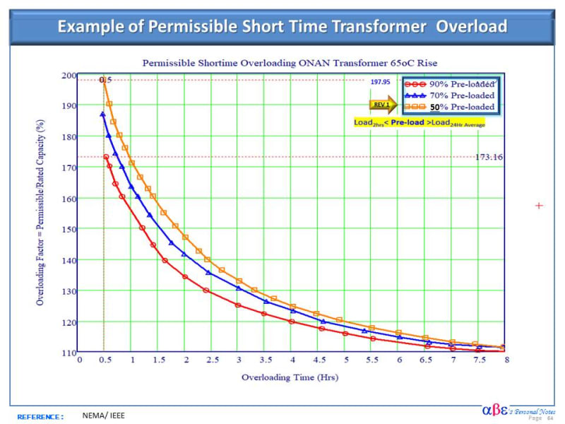
There is a typo error. The orange graph is for 50% preloaded condition.

Please notice that as higher is the preloading on the transformer, lower is the allowable overload. At 50% pre-loading, the transformer should be capable to virtually double the self-colling kVA capacity. That makes sense since the thermal energy capacity of oil/winding/core assembly will have more capacity to absorb heat during the overload scenario if preloading is smaller (less pre-heat).

Transformer rating is based in a daily average standard temperature of 30oC. The enclosed Link provides a correction curve for ONAN/ONAF transformers for a different daily average temperature.

GENERAL COMMENT:
[highlight #FCE94F]RRaghunath:Bracing winding for the cyclic load is a legitimate concern, particularly in large power transformer. However, from the cost perspective, I am not sure for a small distribution transformer (~100 kVA) available off self what could be the best option to pay a premium price for custom made transformer or just purchase a later time or have available a spare unit.[/highlight]


Below is a revised curve correcting the orange value.

Short_Time_Transformer_Overload_uqbryc.jpg
 
Loving this thread. How does this compare to medium sized power transformers if I may ask?
 
Let me express some contrarian views:
1) Cyclic loading is quite common in many applications of transformers and normal standardized construction is capable of handling them. Eg: Rail track supply transformers. 10-100 MVA 33-400kV supplying power at 25 kV AC to overhead traction catenary. Loading will be continuously varying depending on train traffic. These are also subjected to frequent short circuits. Another application is furnace transformers.

Indian Railway Track side supply Transformer Specifications:
21.6/30.24 MVA & 30/42 MVA ONAN/ONAF Ratings
150% loading for 15 minutes and 200 % loading foe 5 minutes over ONAN rating and 150 % loading for 15 minutes on ONAF rating. Temperature rises of oil /winding/hotspot shall be 40/50/65 C under 100 % loading and 40/60/65 C under overload.

2) Please use IEC or IEEE loading guides instead of graphs proposed by Cuky2000. They incorporate many of the latest learnings. But in general avoid over loadings esp.old units that may be wet. As per IEC 60076-7-2017 Loading Guide,Maximum short time overloading limits for distribution transformers is 2.0 pu, medium size 1.5 pu and large units 1.5 pu. For normal cyclic loadings the respective limits are 1.5,1.5 &1.3 pu. Don't forget the risks involved with such loadings and excess loss of life with it.

3) waross is right. All transformers are subjected to pulsed loading when they are switched on (inrush current can be as high as 10 pu) or put on a motor.

4) There are some special loads that we call pulsed loadings- few cycles 100 % load, then zero load for few seconds and then repeat. These transformers are required by Nuclear labs.


Those curves were developed for a small distribution transformer per IEEE Std C57.92 as originally posted (75 kVA?). I believe that is also applicable to medium-sized power transformers following the notes of cautions as state below. It should be noted that this approach was followed by several larger US utility in the US for many years with fairly good degree of success and still some of them are used in their loading of power transformers.

Mos recently and extended to larger power transformers, base in IEEE Std C57.91 or IEC Std 354, It is a common operational practice to address normal life expectancy, Long-time emergency, and even Short-time emergency loading.

Utilities in the US often use the EPRI PTLoad v.6.2. software to predict the allowable load under a particular overloading scenario. Occasionally, the hard decision is made to scarify some loss of life went there are no other choices.

NOTE OF CAUTION: Engineering judgment is suggested to be on the conservative side with a reasonable safety margin for overloading the transformer beyond the nameplate since there is a danger of the winding temperature exceeding the critical temperature. The following is recommended:
1) Considering the large disparity of time constant of the oil (2 - 4 hrs), and the time constant of the winding (2-6 min), bring uncertainty to determine the accurate permissible duration of the overloading.
2) Max. hottest spot temperature should be kept under the stipulated in the standard.
3) Transformers without OLTC have a better chance to be overload since the LTC is one of the most prominent limiting factors is the ancillary equipment ratings which include the thermal rating for bushings and load tap changers.
 
Hi PRC,

We welcome the contrarian views because this helps us to arrive better understanding of the subject.

It is a common practice in the electrical power industry to overload the system if requires to avoid blackouts. Most utilities follow the standard and their own general guideline.

Below is a quick comparison of the IEEE and IEC regarding transformer loading limits and some tables with accepted operational practice to the overload power transformer. Please notice that the maximum overload beyond the nameplate for short term emergency is 2 pu (200%) of the transformer self-cooling rating. There is a general consensus not to exceed the maximum hot spot of 180 oC for transformer manufactured for the IEEE Std and 160 oC per IEC.

I hope this brings further clarity to the subject.

Transformer_Overloading_IEEE_IEC_xqgqh0.jpg
 
What force causes the winding strain RRaghunath mentioned?
1) Magnetic forces in excess of design loads? Would 200% load with a duty cycle 25% put twice as much mechanical force on the winding blocking? Or would it be four times as much force?

2) Thermal fatigue repeatedly heating/cooling of the winding and/or transformer? An example of this could be failure of early wind farm transformer failures. Would a 4 minute period be fast enough compared to the thermal time constant to avoid this kind of failure?

3) A transient associated with turning a load on or off? Would a load that ramps from 0% to 200% be any less damaging than one that steps directly from 0% to 200% loading.

 
bacon4life,
1) Force on windings (radial and axial) varies as square of the current.

2) Winding brazing design is done for the short circuit current ie 6-12 times full load current depending on impedance; ie 36-144 times the normal working forces at full load. Hence such cyclical overloading or shock loads will not cause any damaging strain on windings. Rail track supply transformers are subjected to such fluctuating loads all along.

3) To my understanding, there is no thermal fatigue. Wind farm transformer failures were due to some other issues.

4) 0-200% loading creates more shock than ramping up load; may not be damaging
 
Status
Not open for further replies.

Part and Inventory Search

Sponsor