Continue to Site

Eng-Tips is the largest engineering community on the Internet

Intelligent Work Forums for Engineering Professionals

  • Congratulations KootK on being selected by the Eng-Tips community for having the most helpful posts in the forums last week. Way to Go!

Self-Tuning PID Controller to implement in a PLC without having the plant model?

Status
Not open for further replies.

choguerrero

Electrical
Sep 22, 2015
2
Hi Everyone,

I need to implement a Self-tuning PID controller in a PLC. I know the behavior of the plant (I mean, I know that if the speed is reduced the tension get high and vice versa), but I do not have a mathematical model of it. Which method for an adaptive (self tuning) PI Controller would you recommend?

My case is the following:

I have a system which consists of a warp beam in which a yarn is wound and an AC motor to rotate the warp beam (“Process” according to the picture below). This yarn should be fed at a constant tension to another machine (The whole system is a weaving machine, but I am just controlling the speed of the warp beam using a tension sensor). The motor is connected to a control motion system in which we have just to specify the speed at which the motor should rotate, so we have a PID controller to calculate the speed at which the motor should run. To measure the tension of the yarn we have a tension sensor.
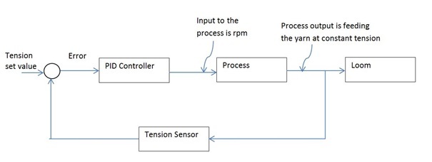
Process_wq4r7o.jpg


By the nature of the process itself, the tension on the thread has oscillations, and depends of the pattern of the woven fabric and speed. It is a “high speed” process. So we specified a target tension, which the “motor” should try to achieve, but we also specified a Max. and Min. if the tension gets out of this range the whole machine will stop.
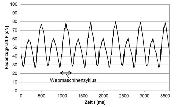
As an example the behavior of the tension in a loom is depicted below.
For a rapport 4
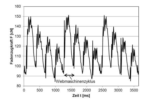
Rapport4_hsptac.jpg


For a rapport 2
Rapport2_ozrual.jpg


Any comment, advice, suggestion are welcome.

Thanks in advance,
 
Replies continue below

Recommended for you

You may want to ask a DIFFERENT question instead: why am I using a PID to control VELOCITY when what I REALLY want is a PID to control Tension (torque)?

Consider inviting in some folks who sell tensioning systems and ask them to critique your present system and offer a better way? I think you will get the solution you want, a lot faster and easier, than trying to make some adaptive control "patch/bandaid" around an incorrect basic loop as you presently have.


High-speed weaving involves very jerky motion of the yarns, so inertia of the yarns and tension sensors has a large affect on actual and measured tension (which may not be the same thing). Not all problems can be solved with mathematics alone, although math might help to understand the problem.
 
As Mike points out, if it is at all possible to operate on a tension-torque feedback loop instead, that would almost certainly be preferable. VFDs have PID logic embedded that will cause the motor speed to adjust to supply the desired torque and hence achieve the desired tension. How are you driving the warp beam motor?

But disregarding that; since I am a curious novice to web tension control, why do you need a self tuning PID loop for something like a weaving machine? Are your environmental factors really that variable?
 
From your diagrams it looks like the tension can vary rather quickly, might be faster that a motor and drive can respond. If that is the case you will probably have to have some type of mechanical tensioning device to handle the high speed changes and use the motor to cover the long term low speed adjustments.
 
Thanks for your replies.

The whole context is the following: the weaving machine is not in the industry but in a research institute from a University. They modified the machine that instead of having just one big warp beam, 10 smallest warp beams are used. and now we have a controller for the loom and another controller for the motors, which feed the yarn to the loom.

The motors are controlled through a motion controller from Siemens:
Simotion D445-1
SINAMICS S120 (CU320_2_DP),
Smart Line Module: Input 3AC, 380-480V 50/60HZ, Output: DC 600V 27A 16kW.
5 Double Motor module: Input DC 600V, Output 3AC 400V, 1,7A.

All the hardware is already connected and the drives are configured to work as speed control (I received it this way), we just specify the speed at which the motors should run. for that a PI algorithm is used to calculate the rpm of each motor.

The behavior on the yarn tension is cyclic and depend on the strength of the material used, speed at which the loom is running, the pattern of the fabric that is being woven, among others... So because of that, the loom is set to run always at the same speed, and every time that the material of the pattern is change, the Kp and Ki have to be changed manually. otherwise entanglement or break of the yarns could happen (and actually it has happened).

Now I doing my thesis with this process, and initially the idea was to implement an adaptive PI algorithm to compensate the variations of the process. I know that this controller (Simotion) is very powerful and indeed torque control will be the best option. but happen that I have not experience with Siemens, and the software has to many things to help the engineers to program the drivers that it becomes to complex for me to reconfigured the drivers to torque control. so I was trying to keep the previous configuration (speed control)

All comments are welcome!
 
Very good! So this is a learning experience! Wonderful!

The issue with trying to patch it with some algorithm is that TORQUE comes before speed.

So torque loops run at typically 1000+hz BW.

Velocity loops are much slower - running around 100hz BW, since velocity is the RESULT of the torque.

Then come Position loops even slower, around the velocity loops - running around 10hz BW, since position is the result of velocity.

So to try to put an adaptive scheme to a 100hz velocity loop when you require 1000hz to actually properly affect the torque, makes no sense.

Really consider learning more about your Siemens controller and see if you can figure out how to make it a torque or current loop instead. Then go from there. I suspect you will need NO adaptive corrections at all by doing it this way?


I'd suggest:

1) Get the system running.

2) The usual way to get a real time transfer function is to inject a low level pseudo random signal into the loop and do a spectrum analysis. This can then be used to set the PID gains.

3) You'll still probably have to set up initial gains based on the thread/weaving pattern.

Is there some way you can get a signal for the tension disturbance? It could be used as a feed forward signal to at least partially compensate for the periodic torque disturbance.
 
As others have responded, I think you will have an up hill battle with the velocity loop servo. I'm sure you have googeld "Tension Control Loops" and found that they are usually a torque control loop with a "Dancer Arm" for torque feedback and high frequency compliance.
 
Dancer arm position is most often used to trim the velocity in a velocity loop. The dancer itself applies and controls the tension of the fiber. Torque control is more common when there is no dancer.
 
You won’t control a motor that responds in about 3.5 times per second as indicated by your charts. My opinion: the motor feed for this process should be nixed. This feed should come from a wound spool that grips the yarn at a steady value based on spring tension, not from a motor that is tasked to keep up with such a variable process.

I hope this thought doesn't derail your thesis...
 
It occurs to me that one area of auto tuning you might look at is to change gains based on the changing inertia of the feed spool.
 
Just for reference, in this size servo motor, the torque can change from 0 to peak in less than 5 msec, so yes, it can keep up with the 300msec changing cyclic load chart shown.

Also as point of reference, we supplied for many years similar size motors to precisely control the torque each revolution of carbon fiber string spools - 24 spools, each with a torque servo motor, all at the same time, independently, feeding carbon fiber winding machinery for aerospace companies; these machine are made every day and the chart above would be a piece of cake compared to their tensioning - assuming you do it as active torque loop instead.

 
Status
Not open for further replies.

Part and Inventory Search

Sponsor