Continue to Site

Eng-Tips is the largest engineering community on the Internet

Intelligent Work Forums for Engineering Professionals

  • Congratulations IDS on being selected by the Eng-Tips community for having the most helpful posts in the forums last week. Way to Go!

Series transformer on primary?

Status
Not open for further replies.

argotier

Electrical
Jan 2, 2020
103
I've been around a few months now and this is my first question for you guys. With all the extra time I have in home, I thought I could use your expertise and clear some old topics I've been struggling with now and then.

I'm somewhat familiar with the concept of series transformers when it comes to the typical connection (see A below), with a regulating winding of a main unit feeding the primary of the series transformer and its secondary connected in series with the secondary of the main to increase or decrease its final secondary voltage (Us).

That's not the problem.

The problem for me begins when you consider a different arrangement, with the series transformer connected on the primary side (like B below). This circuit is not discussed in any book I've checked, and I've always thought that it wouldn't even work!

To be more clear, the typical circuit assumes that the primary voltage (Up) is constant and you regulate the secondary (Us) (usual IEEE approach) and the alternative B was considered for regulating the primary voltage so the secondary remains constant (like IEC approach).
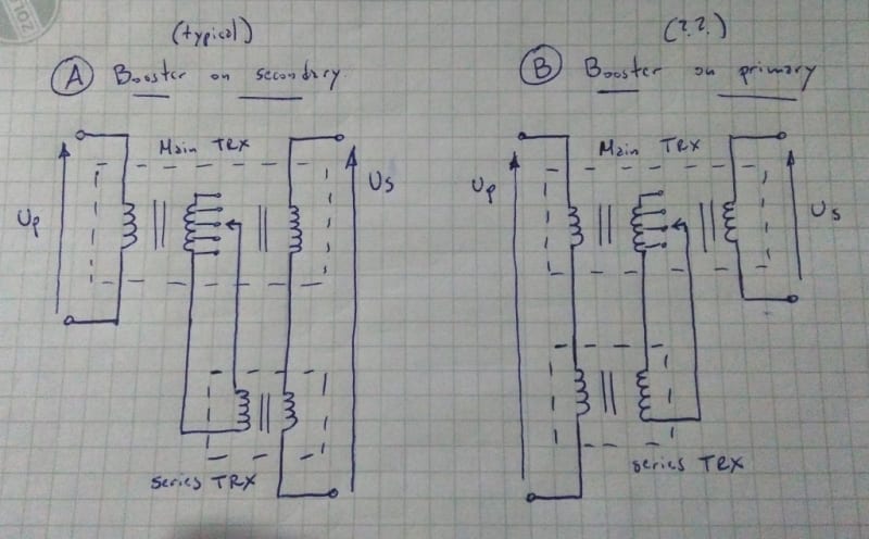
IMG_20200513_194555_tlfrcj.jpg

-Sorry for the messy sketch, some details were omitted or forgotten for more clarity-

So far so good, I was sure that this contraption didn't work and I was happy to defend my views on the subject, always as a theoretical exercise.

Now the problem: a few years ago I stumbled across a "living proof" that I was wrong all along and indeed this kind of circuit B existed and was used at least on one power transformer.

My question is: if this circuit B works, how??? I mean the concept behind it. I can't wrap my head around it.
 
Replies continue below

Recommended for you

A tapped winding is used to drive a series transformer.
The voltage of the series transformer depends on the tap position. You knew that.
Now, the voltage developed by the series transformer may be added to the primary voltage or to the secondary voltage.
There is a little kink in the second circuit.
As the series transformer adds to the supply voltage of the main transformer, the voltage developed by the tapped winding rises also and the voltage added to the primary supply rises.
The calculations for the actual voltage developed by the secondary for a given tap position are a little more difficult.


Bill
--------------------
"Why not the best?"
Jimmy Carter
 
Thank you waross for your reply.

This:
waross said:
As the series transformer adds to the supply voltage of the main transformer
is exactly the thing I'm not understanding.

For the typical diagram the power flow is pretty straight forward, but on B variant there seems to be some kind of feedback on the primary that I'm not sure how it works.
It's supposed that the series transformer it's energized by the regulating winding but what stops the supply voltage from energizing the booster and end up with two windings in parallel (reg and secondary of series).

On my sketch can't be seen but there is a tap position (the rated voltage one) where there is no turn in the regulating winding involved and the secondary (or primary, I don't know how to call it in this case) of the series trx it's short-circuited. To my eyes that is a series trx energized from primary voltage with its secondary short-circuited! What is "balancing" the voltages across both primaries to avoid a failure here? (<- maybe this is the key to my doubts).
 
Let's put some numbers to the transformers.
Supply voltage = 1000 volts.
Booster tap ratio = 10:1
Output voltage = 100 Volts
Booster voltage = 1000/10 = 100 Volts.
1000V + 100V = 1100 Volts into the main transformer primary.
The output voltage is now 110 Volts.
BUT;
The boost voltage also increases 10% and is now 110 Volts.
1110 Volts input = 111Volts output.
BUT;
The boost voltage also increases 10% and is now 111 Volts.
1111 Volts input = 111.1 Volts output.
The boost transformer must be capable of the current and voltage that it will encointer.
If the boost transformer is on the primary, it must be suitable for primary voltage and primary current.
If the boost transformer is on the secondary, it must be suitable for secondary voltage and secondary current.
The boost transformer need not be part of the main transformer.
It may be a separate transformer.
It may be easier to understand if you consider the boost transformer as a separate transformer.
This scheme requires five windings.
A tapped auto-transformer will do the same thing with only one winding.

Bill
--------------------
"Why not the best?"
Jimmy Carter
 
Wait a moment, I think I didn't explain myself good enough (sorry, English is not my native language).

For the alternative B shown above the idea is to keep the secondary voltage (Us) constant while the primary voltage (Up) varies with the grid.

So the voltages in the primary must "balance" in some way like this:

Up supply (varying with the grid) = Up main (constant) + Up series (varying with the tap changer)

The tap changer must operate to compensate (through the series transformer) the variations of the supply voltage allowing the primary voltage on the main trx to remain constant, wich will result in a constant secondary voltage (Us) as desired. This has the advantage that the main trx will work with constant magnetic flux and only the series will work with varying flux (same as typical connection).

Is this "reverse" power flow (primary of main -> regulating winding from main -> secondary of series trx -> back to primary now of the series trx) wich I find counter-intuitive and reluctant to believe.

But your advice:
waross said:
It may be easier to understand if you consider the boost transformer as a separate transformer.
may prove to be useful. I'll have to think a bit more.

Thanks again!
 
Look at another way.
The grid voltage is applied to transformers connected in series.
One of those transformers is energized.
The grid voltage, plus the voltage of the energized transformer will be the voltage that is applied to the main transformer.
Not shown on the sketches is the polarity of the booster transformers.
When the booster is on the secondary, the polarity is such as to add to the voltage of the main transformer.
When the booster is on the primary, the polarity is such as to add to the line voltage.
With the booster on the secondary side, the booster adds to the transformer voltage. The line out voltage is greater than the main transformer voltage.
With the booster on the primary side, the booster adds to the line voltage and the main transformer voltage is greater than the line voltage.

Bill
--------------------
"Why not the best?"
Jimmy Carter
 
Actaully option (B) is for varying the voltage at primary terminals. The series transformer can be separate transformer or on side limb of main core. Tappings can be provided in the exciter winding of series transformer instead of in the tertiary winding of main unit.

To take care of power flow ampere turns in any magnetic limb should be equal ie exciter winding AT = boost winding AT on primary side;secondary AT = primary AT (with out boost winding) + tertiary winding AT

This type of windings were quite common in EHV auto-tarnsformers till OLTcs were developed for line end applications.You can still find them in many countries for EHV auto transformers (765 Kv auto trfs in India) and MV transformers with very low voltage difference between primary and secondary. Now voltage regulators with boosters are getting popular where renewables are feeding to MV grid.
 
Status
Not open for further replies.

Part and Inventory Search

Sponsor