Continue to Site

Eng-Tips is the largest engineering community on the Internet

Intelligent Work Forums for Engineering Professionals

  • Congratulations IDS on being selected by the Eng-Tips community for having the most helpful posts in the forums last week. Way to Go!

Several cooling tower pump motors burnt

Status
Not open for further replies.

SA07

Electrical
Feb 22, 2018
366
Hi
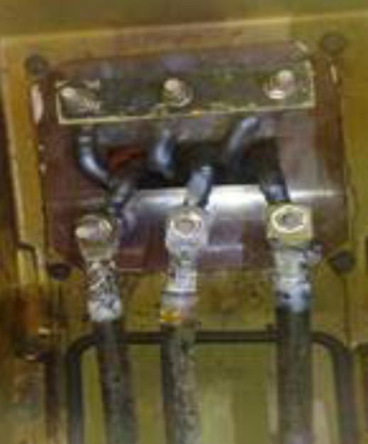
We had several breakdown on cooling tower pump motors since 2014. There were cables/lugs heated inside motor connection box. In 2020, since April to June, 3 motors were burnt.

We have 2 independent cooling towers for 2 turbo alternators 45 MW.
Motor nameplate :
350 kW , 742 rpm General Connection Diagram , Stator 400 / 690 V , code 9101 , Space heaters 9410 , Temp.sensor in the windings 9024 , bearings 9034 , 3 ph induction motor , mod HFG 355D , 50 Hz , , SF 1.0 , 400 / 690 V , 657,6 / 379,6 A , code G , IP 55 , Ins F , iL/iN 7 , Duty S1 , Nr : 1598190806 , AMB 40 °C , Δt 80°C , cos φ 0.8 , ALT 1000m , cooling C411 , 3190 kg , AV. PREF Waldemar ,Grubba 3000 , 89256-300-JARAGUA DOSUL SC CNPJ-07.175.725/0009-17 , Made in Brazil.

Supply voltage is 690 Vac.
We notice that the cables from the winding to the motor connection box is 95mm2. The motor nominal current is 379A. Is the cable size enough for the nominal current?
Plz see some measurements below:


14.10.14 @10.45
Motor Connection Winding temp
body box on scada
1CRF001MO 56 47 88.3
1CRF002MO 55 46 84.8
2CRF001MO 60 56 105.8
2CRF002MO 54 44 100.2


02.02.15 Current % Current A Winding Temp/DegC

Motor 1 91 345 110.1
Motor 2 91 345 105.8
Current & temperature winding

11.10.14 @11.32 13.10.14 @9.45
Current % Temp Winding Current/A Current %
1CRF001MO 89 91 337 89
1CRF002MO 89 88 337 89
2CRF001MO 91 108 343 91
2CRF002MO 91 102.7 343 91

Sometimes we have noticed water inside the motor connection box.

When we stop for annual maintenance or trip, we import power from the utility grid and run only 1 pump to save on power import. After we synchronise with the grid, we run the 2nd pump and the 2 fans. During the start-up period, there is water splashing around the cooling tower and on the motors. Can this water cause the motor to burn?

Has someone encounter similar problems with cooling tower pump motors?


Plz see attached pictures for:

Cables/lugs burnt in motor connection box

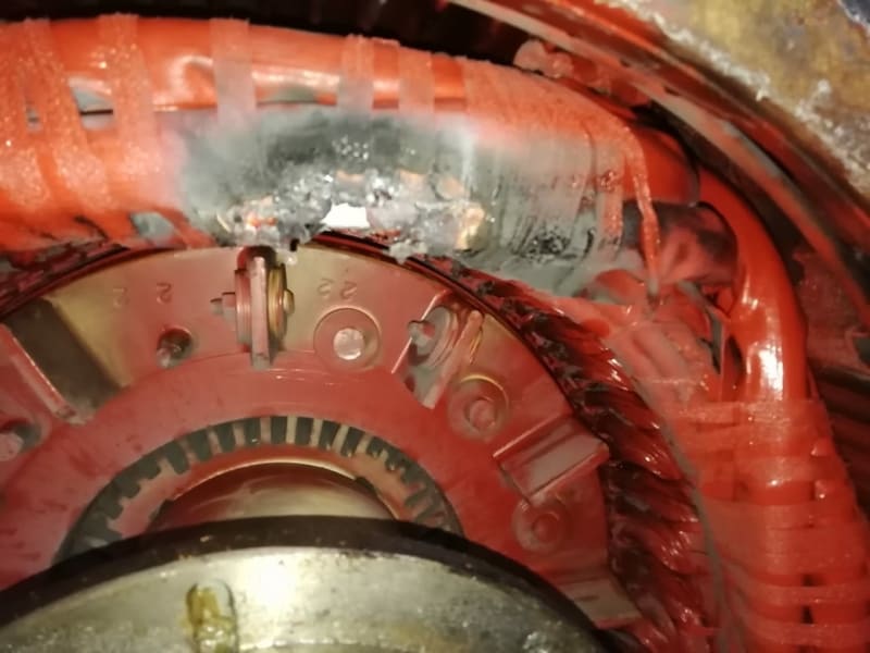
Latest motor winding damaged

 
 https://files.engineering.com/getfile.aspx?folder=7ae6b0dd-75aa-4b0c-9cf9-66e487257369&file=Cooling_tower_motor_burnt_connection_box.docx
Replies continue below

Recommended for you

Here folks are the 2 pictures.

pic1_zirtbl.jpg


and

IMG-20200702-WA0001_ii3eoi.jpg


Keith Cress
kcress -
 
It appears that the failure of the winding may be where the lead connects to the winding.
The heat generated by a loose connection will conduct down the lead wire.
I have seen other cases of secondary damage caused by the heat from a poor connection being conducted by a copper cable.
It looks as if the connections were not tight enough.
Possibly the connection was not properly cleaned before assembly.
Possibly both.
I have known electricians like that.
For a time I was forced to use a crew like that.
I learned to check all major connections for tightness after they had finished.
I had no more early failure of connections once I started checking and tightening properly.


Bill
--------------------
"Why not the best?"
Jimmy Carter
 
Hey Bill, as well as pre-burnishing and providing tight connections, have anti-oxidant and/or conductive pastes played into your experience? How about potting / encapsulating the connections?

CR

"As iron sharpens iron, so one person sharpens another." [Proverbs 27:17, NIV]
 
crshears said:
Hey Bill, as well as pre-burnishing and providing tight connections, have anti-oxidant and/or conductive pastes played into your experience?
Yes, often.
Aluminum alloy set screws on bus strips and breakers. I always look for Penetrox.
Terminating stranded copper conductors. I often use Penetrox.
Aluminum. Anything involving aluminum needs Penetrox or similar.

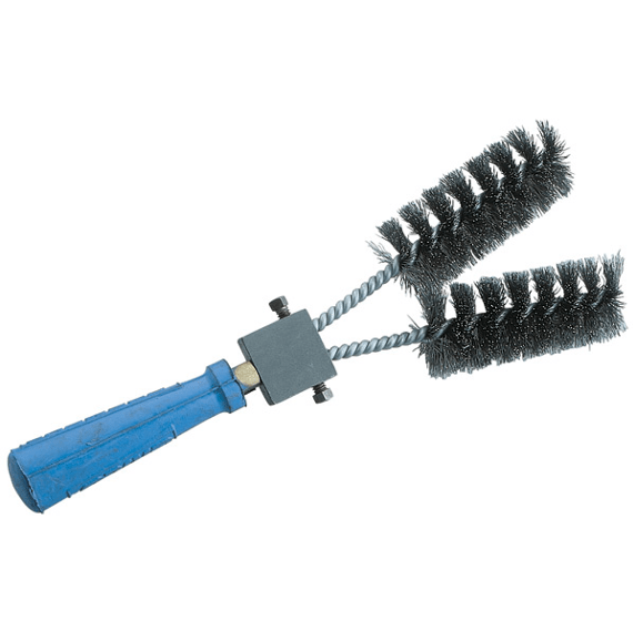
Burnishing stranded cables prior to connecting.
This brush from Erico, the Cadweld people does a good job.
I have bent the brushes to be more parallel. (Can something be "more parallel"? You know what I mean)
image_w4igyr.png

In regards to flat strip conductors:
I have connected generators that were wound with multiple flat strips rather than round or square conductors.
This reduces eddy current losses in the windings.
The end of each individual strip was burnished both sides and treated with Penetrox before being connected.
I have assembled spaced, laminated 6" x 1/4" bus bars where the spec called for cleaning or burnishing, application of Penetrox or similar, and burnishing again with a wire brush, through the Penetrox coating.
This was very messy, but the spec is the spec.
Thanks for asking cr.

Bill
--------------------
"Why not the best?"
Jimmy Carter
 
I think Bill's suggestion is plausible. There's no doubt heat conducts very well through copper. The location of the failure is in the endwindings on the connection end circuit ring which could very well be connected directly to the T-leads.

Imo it's also worth considering another scenario: degradation of a winder-made connection in the endwinding at the location of the failure that has degraded (you could probably tell by closer inspection of the fault area whether or not that is the location of a connection).

Is it likely to have two different unrelated problems (loose field terminations and degradation of winder made connections)? In general that's not likely... but not impossible.

The insulation on those leads entering the motor looks a little thermally damaged but not all that bad. I don't see evidence of heating on either side of that winding fault in the endwinding which might be expected if heating conducted by copper from remote high-resistance connection was carried along this entire path. These factors push my thinking towards the winder-made connection fault, but by no means conclusive. Again a closer inspection of that failure area could show if it is the location of a winder-made connection and therefore give an idea whether my scenario is even plausible. While you're at it, map out at the discoloration patterns of the T-lead and the circuit ring to get an idea of which areas have seen overheating.


=====================================
(2B)+(2B)' ?
 
(Can something be "more parallel"? You know what I mean)

Sure, as long as it's less divergent [bigsmile]

CR

"As iron sharpens iron, so one person sharpens another." [Proverbs 27:17, NIV]
 
Thanks for the support Pete.
Take a look at the heating patern on the winding end.
Does it seem to be spreading in the direction of the T lead, but not so much in the other direction?

Bill
--------------------
"Why not the best?"
Jimmy Carter
 
I see what are probably balancing weights attached to the fins of the rotor with a screw and nut. This does not seem very secure. Are there any missing weights that may have come loose and damaged the winding (indicated by an empty hole in one of the fins)? I think I see such a hole in the lowest right fin.

The winding damage does not show indications of slow overheating but rather a momentary arc.
 
Clearly there is some gray ash that has spread out over the surfaces (under the wraps) after the fault. I see that grey as a surface condition, not an indication of overheating the depth of the insulation (for that I'd expect texture change creating non-smooth surface in addition to color change). I'm admittedly reading a lot into a fuzzy picture.

Another way to think about it is the temperature profile of the conductor. Assuming that loose connection in the t-lead terminations is the source of the heat, then the highest conductor temperature is at that location and the conductor temperature trails lower as we move away from that location. On that basis we expect more damage at the location of the t-lead terminations. Sure the circuit jumpers are more tightly-bundled which provides thermal insulation... but that area cannot end up hotter than the t-lead terminations or else the heat would be flowing the opposite direction (from circuit jumper to T-lead terminations). Maybe the insulation used in the endwindings has lower thermal rating than the t-leads... it would not be typical but it's possible.

For me personally, I would lean toward initiation at the winding connection, but it's a coin flip without more info.

=====================================
(2B)+(2B)' ?
 
The last breakdown ie flash on the winding is not representative of the previous problems on the 4 motors. The usual problem is lugs, motor leads and supply cables heated up inside the connection box. When we stopped for annual maintenance or a planned stop, we noticed this heating up inside the connection box.

We rewinded/repaired the motors locally in Mauritius at a workshop. At 690 Vac, should special varnish, insulating materials be used or any special furnace?

Should we replace the gaskets on the connection box, heater, thermistor boxes. The motors were installed since 2006. Any special silicon to be used to prevent water ingress?

I think I read somewhere on Eng-Tips that motors after they start up, a vacuum is created inside and they may suck water/humidity inside. Is this correct? In one case, we saw water inside the connection box. The rewinder also said after dismantling burnt motors, he noticed water inside them.

Do you think if we put a cover over the motors like a U shape while allowing air to flow, this will reduce water ingress inside the motor?
 
The usual problem is lugs, motor leads and supply cables heated up inside the connection box.
This is often caused by poor workmanship. Surfaces not well cleaned, connections not tight enough.
The cover over the motor sounds like a good idea.
Water inside the connection box:
Sometimes water will run down the cables and enter through old, dried out gland connectors.
I had some generators compromised that way after the hurricane blew the roof off of the powerhouse and then poured brackish water on the sets.
You may be well to install good gaskets. Don't forget the gasket between the junction box and the motor itself.
There is not always a gasket there, but you can install one.

Consider installing anti condensation heaters.

Bill
--------------------
"Why not the best?"
Jimmy Carter
 
If you have occasions where cool water lands on hot motors they definitely will suck in water. To avoid that the motor needs to be vented in a way that prevents the vacuum caused by a quick water chill from forming. If there's a vent then there's no vacuum to suck in water.

On that size motor a 3/4" vent of some sort would probably be enough. Possibly drill and tap a threaded hose barb into the connection cover. Install a quality hose and run it somewhere water cannot reach the opening. Mount it vertically facing downward. Preferably you'd want any water to have flow upward a couple of feet to reach the motor. That way it would not maintain a water plug and would break-up and self drain. Include a little screen or something to block bugs.

Keith Cress
kcress -
 
I see that the motor does have space heaters.
These should be on at all times when the motor is not energized.
itsmoked's suggestion is very good.
The best way to keep sealed electrical equipment dry is to have a hole at the lowest point to let the water out.

Bill
--------------------
"Why not the best?"
Jimmy Carter
 
What is the size of conductor that you ran from the controller to the motor, and how was that determined? You say the internal conductor from the lead box to the winding is 95mm2, but you don't mention the field leads. Here in North America, a motor that size would require conductors that are 750kCMIL (MCM), which equates to approx. 400mm2! That would be around 4x the physical size of the ones you identified as 95mm2. Even if your local codes do not require the 125% that we do, you would still need 240mm2 conductors for 379.6A; 2-1/2x the size of the internal leads. The conductors that you show do not look to be ANYWHERE near that size in either case. If your field leads are grossly undersized, heat from them will spread through the entire circuit, including the motor windings.


" We are all here on earth to help others; what on earth the others are here for I don't know." -- W. H. Auden
 
The motors have a heater. The supply cable is 300 mm2 copper. There is a hole at the bottom of the motor.
 
Check to make sure that the heaters energize when the motor is off.
And triple check sealing, you have to make sure that cables are sealed to prevent moisture moving between the strands and under the insulation.

= = = = = = = = = = = = = = = = = = = =
P.E. Metallurgy, consulting work welcomed
 
the cables from the winding to the motor connection box is 95mm2. The motor nominal current is 379A.

That's too low an area for 379A. At the minimum, I would use 2x95 sq mm copper cables from the winding to the motor terminal block.

The failure shown seems to be a workmanship issue. The transition from the random winding multiple copper conductors to motor take-off leads with even thinner wires is a tricky job that requires certain winder skill set.

Muthu
 
The rewinder came and inspect the motor just burnt. He said there is water inside the motor. He also said that the 95 mm2 that he purchased locally might be of poor quality. He is willing to repair the motor free of charge.
 
Status
Not open for further replies.

Part and Inventory Search

Sponsor