Eng-Tips is the largest engineering community on the Internet

Intelligent Work Forums for Engineering Professionals

Shape of the gear tooth fillet by analytic equation? 3

Status
Not open for further replies.

PrintScaffold

Mechanical
Sep 8, 2006
453
0
0
RU
Hello everyone!

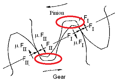
I wonder if formulas exist to analytically draw the shape of the gear tooth fillet (the same way as with the involute shape of the main part of the tooth itself)? I understand that it is being formed by the hob, and essentially is the product of the relative motion of the hob and wheel itself. Is it possible to express this shape by an equation?

image4.png


Replies continue below

Recommended for you

You don't want that - you need clearance with the gear tooth tip. All that's initially required is to create a clearance shape and compare that to the mating tooth tip for the duration of engagement.

The reason the involute is approachable is that it does not depend on the mating gear tooth shape; it only depends on the base radius. The clearance you are looking for involves the number of teeth in the mating gear, the number of teeth in the target gear, the amount of addendum on the mating gear, and tooth tip modifications which may not have a formulaic description.

Decent gear design software will allow you to generate the tooth-tip path and allow you to create a clearance in the mating gear or you can use an extra-long addendum tooth in the cutter and let that create the clearance for you.

Here's a direction start
 
Yes; equations are available that will allow you to plot the generated curve in this area, known as the 'root trochoid'.

You need to get hold of these books;

Gear Geometry & Applied Theory by Faydor L. Litvin

Analytical Mechanics Of Gears by Earl Buckingham

On The Geometry Of External Involute Spur Gears by T. W. Khiralla.
 
Print

excellent advice from every one.
most call outs on Blue Prints are a minimum radii at the root.
do not over think it. if you blend the involute to the root dia
it should be satisfactory. try a stress analysis just for GP.

Mfgenggear
 
The exact profile of the root area depends on the particular type of gear and the application. As noted, it is important to ensure the root profile does not conflict with the active profile and provides adequate clearance for the tips of the mating gear teeth. It is also beneficial for bending stress that the transition from the root fillet profile to the active profile be smooth.

Since the root fillet is usually the location of highest tensile stress, with high-performance gear applications the exact shape of the root fillet can be very important. As a minimum, a full radius root fillet is specified. But sometimes more complex shapes than a simple full radius are used (such as conic profiles) that provide a more uniform stress distribution. Optimizing the exact shape of root fillets by analytical techniques has been the subject of much research since it can have a significant effect on fatigue life.

With spur gears that are form ground it is not difficult to produce almost any root fillet shape you want. With spiral bevel or hypoid gears, where the tooth thickness/space width/depth varies from toe to heel, it is not quite so easy to produce an optimized root fillet shape along the entire tooth width.

A good analytical approach for evaluating involute geometry gear teeth root fillets is given in AGMA 908-B89 sections 5.7 to 5.9.
 
Terry

excellent notation.

Print
just want to add that depending if this gear if it is gear cut or ground.
like terry said will basically will form the radii naturally. be it generated by hob, shaper cutter, form tools, form grinding, or worm wheel grinding.
that is why most drawings specify a minimum fillet radii. on occasion
when a specific root radii is required it will require special handling.
full radii are not hard to obtain but will require a cutter with
full radii. and depending on the CTT and root dia of the gear. it may or may not be a special
order cutter. but be as it is, a reputably gear manufacture can handle that with no problem.

well I think we are probably are killing this post with more than what you asked for.
Mfgenggear
 
The thread would have been much shorter if the question asked in the OP was more specific. If the question asked is not specific, we should provide responses that address every reasonable situation that the person asking the question should consider. The OP only provided a 2D sketch of a pair of external gears, with no other specific details.

Just out of curiosity, why are the two arrows in the sketch denoting rotation of the mating pinion and gear both shown clockwise? Shouldn't one be counter clockwise?
 
Thanks for all positive responses, it gave me a lot of valuable info!

As for negative responses, the amount of negativity was quite surpsising. I have no idea why the original guy pointed arrows how he pointed them, I merely googled this picture. Please do not bring at least this against me.

 
PrintScaffold- I was just asking an honest question. I did not intend to insult you with it. You posted a sketch along with a question that was a bit short on details. I saw something in the sketch that did not make sense to me, so I asked about it.

Personally I'm always happy to help. But in order to get specific answers you need to provide specific details. Otherwise, as you can see from the responses above you will get all sorts of answers that may or may not help you. Gear geometry is a very broad and complex subject. I have rarely used the particular root fillet geometry shown in your sketch where the fillet radius used is so small. There is no reason for it, and there are benefits for using as large a root fillet radius of curvature as practical. Obviously this would affect the approach you would want to use to calculate the shape of your gear's root fillet.
 
tbuelna,

I'll guess it's the direction that torque is applied; the contact points are labeled with force components. Seems like the OP could have credited the image with source. I'm thinking the OP is working on something for his website, devoted to CAD, hence the need for an equation, not from a need to understand gears, but as a modeling shortcut.

I looked at the doc that gearcutter suggested; pretty interesting.
I found several others, but nothing as simple as the involute curve formula. I did my first gear tooth generation animation program back in 1990 or so, so what would I know?
 
I have interest towards modeling of exact gear geometry, that's right. But it's not for the website, it's more like for the general research towards my CAD software capabilities for modeling of complex curves. I got quite interested with the root shape, because it is generally not covered in the reference materials I have at my disposal. I thought that it should not be beyond maths to have figured out the equations for the task.

As for crediting image with source... I did not occure to me in all honesty. Has the humanity became copyright-obsessed to THAT extent?

 
If you really need to do it you'll find the calculations method in:

Dudley's Gear Handbook by Dennis Townsend, editor in chief
In my 2nd edition it starts on page 6.3

Any modern higher level CAD is able to do it if you know the math describing the curve and the user's programming language used by that CAD.
Long time ago we created pretty complex 2D/3D parts (including gears with involute flanks) completely using their numeric parameters as an input in "GRIP" programs in UG (Unigraphics).

 
Since the OP stated his interest was "towards modeling of exact gear geometry", then it would be necessary to understand everything involved with the shape of root fillets. Some gears use a simple radius profile, others have a generated profile that is the result of the machining process used, and some high-performance gears use a complex profile that is the result of an analytical optimization process.

Table 1 from the article linked by 3DDave shows how much difference an optimized fillet profile has on bending tensile stresses. In fact, some gear sets that only transfer power in one direction use different (asymmetric) flank/root profiles on the drive and coast sides of the teeth so that the bending stresses are more fully optimized in terms of fatigue life.

The geometry of gear tooth profiles is quite a complex topic. And I simply want to help the OP understand all the issues involved, given his stated desire to learn about high-fidelity modeling of complex curves/surfaces like those of gear teeth.
 
Status
Not open for further replies.
Back
Top