Continue to Site

Eng-Tips is the largest engineering community on the Internet

Intelligent Work Forums for Engineering Professionals

  • Congratulations KootK on being selected by the Eng-Tips community for having the most helpful posts in the forums last week. Way to Go!

Shear flow question

Status
Not open for further replies.

EngDM

Structural
Aug 10, 2021
389
Hey all,

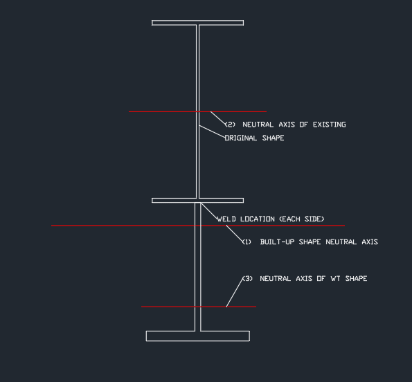
I'm trying to calculate the shear flow to size a weld for a W shape pre-engineered frame. I can't seem to find a procedure to calculate shear flow when the addition of the reinforcing (in my case a WT) lowers the neutral axis below the weld.

In all of the examples I can find, the area in the shear flow equation is described as being the area above the weld. Now I've come to understand that if I am reinforcing the bottom of a beam, it is really the area towards the extreme fiber. However, since the neutral axis is now in the WT reinforcing, I am wondering if the area I need to take for the equation is the area of the existing member (above the weld), or of the WT (below the weld). And subsequently, the distance would be either from lines 2-1 or from lines 3-1 respectively.
Shear_flow_ujg6ad.png
 
Replies continue below

Recommended for you

Flip it upside down and pretend you are adding the wide flange to the bottom of a WT. The shear flow is the same.
 
Agreed. If I recall correctly, you equation is VQ/I and Q is equal whether it's considered for the reinforcing piece, or for the existing steel.

In your case, I`d consider A-ybar for the new steel below the neutral axis, then subtract a-ybar for the new steel above the neutral axis.
Compare that value for a-ybar of the existing wide flange beam.
If my memory is correct, they`ll be equal.
 
ryaneng said:
Flip it upside down and pretend you are adding the wide flange to the bottom of a WT. The shear flow is the same.

So it is indeed taking my area as being the area of the wide flange, not the area of the WT.

Once20036 said:
Agreed. If I recall correctly, you equation is VQ/I and Q is equal whether it's considered for the reinforcing piece, or for the existing steel.

So since they are equal, it would be easier to flip the shape as suggested so that I don't need to subtract area of the WT above the neutral axis; I'd only be using the area of the wide flange.

Edit: I've verified that calculating based off of the WF area and the ybar from global N.A. to WF N.A is equal to taking the area below the global N.A. of the WT shape * ybar of this broken shape, and subtracting the area above the global N.A and multiplying by the ybar of this small rectangle.
 
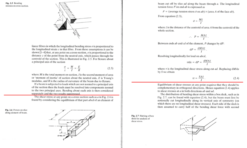
Here's the physical meaning/derivation of VQ/I, which is written as S*(A*z)/I in the last equation. I find this useful to understand what you're actually calculating. Basically, the varying bending moment causes the axial stresses to vary along the length of the beam. When you integrate them at two sections, you get two different axial forces, with the shear flow being the force required for axial equilibrium divided by the length between the two sections.

Another way of thinking about it is the weld needs to transfer more force into the reinforcement element when the bending moment increases. In your case, part of the reinforcement is in tension and part is in compression, which is why you subtract part of the area when calculating Q, as the net tension force is reduced by the compression component.

This way of thinking can help when you're not in an elastic situation, as VQ/I is only valid for linear-elastic stress distributions. You go beyond this when the section starts yielding, or in cracked composite concrete sections.

HamblyShearFlow_xivywz.gif
 
Great picture, dik, but the shear stress is not zero at the neutral axis - it is typically maximal at that point.
 
centondollar said:
Great picture, dik, but the shear stress is not zero at the neutral axis - it is typically maximal at that point.

The picture describes it as being the area from where shear flow is being calculated and where the shear stress is zero, which is the extreme fiber. The picture appears to be correct.
 
The shear stress is calculated at the distance y. The top steel beam would be the A' value and the distance from the composite centre to the centroid of the top steel beam would be the ybar value. It gives the connection shear at the intersection of the W and the T.

-----*****-----
So strange to see the singularity approaching while the entire planet is rapidly turning into a hellscape. -John Coates

-Dik
 
I stand corrected. The wording is weird, though. I would not describe the first moment of area as done in that picture.
 
The website I copied that from was by accident and I thought it was one of the easiest explanations I've come across... Catch the attached programs... Had a project with a bunch of these a couple of weeks back and updated my SMath files...

[URL unfurl="true"]https://res.cloudinary.com/engineering-com/image/upload/v1674329365/tips/Comp-W_T_qnyxtq.pdf[/url]

[URL unfurl="true"]https://res.cloudinary.com/engineering-com/raw/upload/v1674329365/tips/Comp-W_T_r90svl.sm[/url]

-----*****-----
So strange to see the singularity approaching while the entire planet is rapidly turning into a hellscape. -John Coates

-Dik
 
Status
Not open for further replies.

Part and Inventory Search

Sponsor