Eng-Tips is the largest engineering community on the Internet

Intelligent Work Forums for Engineering Professionals

Shear flow, stacked wooden beams

Status
Not open for further replies.

Eagleee

Structural
Feb 14, 2017
51
0
0
DK
Apologies if in my brief search I missed threads which would clarify my below question. For the calculation of some wooden members, I was recently confronted with the problem mentioned in this post. I note that since then the matter was fully resolved in another way (unrelated to this post), so this post basically represents an itching curiosity of mine.

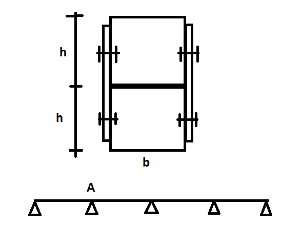
Consider a multiple span beam as shown in the attached sketch. The beam is built up from two identical members on top of each other, c.s. dimenions b x h. The intention is to fasten them together on their sides, so I am interested in this specific problem and not, for example, if there is a better structural solution to achieve composite action for the members. The question is how to calculate the spacing in the longitudinal direction of the beam between fasteners.

My understanding is that the correct approach would go something like this:

Vmax (at point A) = line load * l * 0.571 (l is spacing between supports)
Q = b*h*h/2 (first moment of area of the top beam)
I = b*(2*h)^3/12 (second moment of area of the full cross-section)
q = Vmax*Q/I (shear flow)
s = 0.5*q/Frd (s - spacing between fasteners, Frd - shear resistance of fastener (including bearing and all other similar criteria)

I then further understand that if needed, instead of Vmax I can use V(l) and vary the spacing between fasteners acc. to how the shear force along the beam varies. The issues I would like to address are:
1. Would you consider the above approach correct? When doing these calculations, with real values, the resulting maximum spacing was much, much lower than I would have expected.
2. I am uncertain of the implications due to the fact that the interface between the two beams and the location of horizontal shear force transfer at fastener locations are not the same. Does anything 'funky' happen with the lower half of the top beam / upper half of the bottom beam? Are they 'engaged' in the current configuration? Any necessary modifications to the expressions above due to this? Does it matter where where the fasteners are located (e.g. if the fasteners for the top beam would be at h/4 from its base compared to h/2 in the sketch)? If so, what is missing / wrong in the expressions above?

Any thoughts are much appreciated.

Screenshot_1_wmibjl.png
 
Replies continue below

Recommended for you

I assume that the plates are discrete plates at the fastener locations. If that is your intention, the plates would just rotate, so no composite benefit would be achieved.

If the plates are continuous, then the steel would be doing most of the work as simple bending members.

As you have discovered, it takes a lot of connection capacity to make stacked wooden members composite. It is an impractical concept.
 
hokie66, the plates are continuous. could you elaborate on what you mean by them doing most of the work? if the connection capacity would be somehow achieved, would you not rely on the bending capacity of the composite cross-section of the two beams? and yes, i am discovering things, i have not done much wood design before so i'm trying to get a feel for it.
 
- is your equation for fastener spacing not inverted?

- I think that Hokie's just asking if your fastener plates are continuous and part of the flexural member, like a flitch beam. I don't believe that's your intent though and that, rather, you just mean for the plates to represent generic fastening.

- with built up wood beams, there are always concerns about whether or not fastener slip effectively neuter any composite behavior. That's a practical concern, however, and may not impact your largely theoretical question.

 
Yes, KootK, equation is inverted, my bad. You are right, my thought was to disregard the plates for bending capacity. Good to know practical common practical concerns like in your third point. The slip issue I assume included somewhere in the calculation of Frd.
 
Also, what does the 0.5 factor represent in your fastener equation? If that's averaging the shear flow, that may not be appropriate where failure mechanisms cannot be assumed to be ductile.

 
Eagleee said:
the 0.5 factor is just due to the fact that forces are transferred on two sides.

Right... sorry to waste your time with such a silly question.

With regard to your second question:

a) I think that your instincts are solid. There is something funky at play.

b) The funkiness is fascinating and I've had to let this ruminate for a couple of hours to get it sorted.

c) I believe that the fastener separation has a massive effect and implies one of the following:

i) If the connection plate is continuous, then it's going to absorb some moment whether you want it to or not. This speaks to Hokie's comments somewhat.

ii) If the connection plates are discrete, then they will deliver moments to both the upper and lower halves of the cross section. consequently, your fasteners would need to resist both the direct, horizontal shear flow AND these moments.

Bloody neat.

 
I should also add that, if you're going with discrete connection plates that would need to deliver moments, that brings th stiffness of the connection, and the viability of composite action, even more into question than if the fasteners were located at the conventional shear plane.

 
no time wasted. trust is good, mistrust is better in this field at the end of the day, right? thanks for the reply kootk, when i’ll have the chance i’ll sharpen the pencil a bit, with such replies in mind. the side plates in my specific case were also wood, which makes matters even more complicated i guess. a bit reassuring to catch seemingly simple things like this, especially because i would expect this to be quite a common solution on sites...you have two types of beams, plywood or similar, want to make them into one beam or column and dont have or dont want to glue them or similar.
 
I think any deformation in the fixings in the box section you created would negate any composite action in my view, or at the very least make it a whole lot more complicated to analyse to account for the slip.

Stepping back to a normal flitch beam for a second, say steel plates either side of full depth timber member, the fixings aren't there to transfer longitudinal shear flow forces. They are there to ensure vertical load transfer between the individual plies and constrain them to the same deformation/deflection. Load is shared based on stiffness of each ply (usual transform section to a similar material and compare ratios). For this scenario depending on the plate vs timber dimensions you might be looking at load on the plates being 80-90% or higher being carried by the steel plates.

Now your scenario is dependant on transferring the longitudinal shear flow forces for achieving any composite action. Which is fundamentally different to a typical flitch beam behaviour, any fastener slip (there will be fastener slip getting to the capacity of the fastener) negates any compatibility strain relationship. What I mean by this is strain being the same in the steel/timber at a given depth.

I believe in this scenario, any slip or long term creep in the timber top and bottom flange of your 'box' basically results in load being shed to the steel plates. Therefore my view is to just use the 2 plates for strength and stiffness, ensure they don't laterally tosionally buckle, compression edge needs some restraint, job done.

You'll get to a point especially with a double plate, whereby the plate stiffness greatly outweighs the stiffness being added by the two timber bits. Sure if the timber added a significant amount of stiffness it might be worthwhile, but it won't. If you were to work out using the long term stiffness of the timber the transformed section stiffness and compare it to the stiffness sum of the two plates, I'd bet the timber contributes relatively little additional stiffness.

Most timber fasteners to reach the code capacity have some limiting slip that is deemed acceptable, this doesn't account for obviously oversized holes in the steel to get the fasteners in. Bolts more so due to oversized holes in both timber and steel, etc. It wouldn't be out of the question to have a code based on achieving a limiting slip of 0.5mm or similar at the ultimate capacity of a fastener.
 
Somehow missed your last post saying its all timber, above post still applies related to the fastener slip.

Creating glued box beams happens all the time, because there is no slip, they work compositely.
 
If you want a down and dirty approach to see if what you are trying to do comes even close, determine the max. moment, divide by the smaller of the 2 wood beams, that is the shear you need to transfer into the top and bottom beam at the location of that moment.
 
Status
Not open for further replies.
Back
Top