Eng-Tips is the largest engineering community on the Internet

Intelligent Work Forums for Engineering Professionals

  • Congratulations waross on being selected by the Tek-Tips community for having the most helpful posts in the forums last week. Way to Go!

Shear key design for to support column in 14-storey building 5

Status
Not open for further replies.

Temporaryworks

Structural
Aug 27, 2017
46
0
0
GB
Hi All,

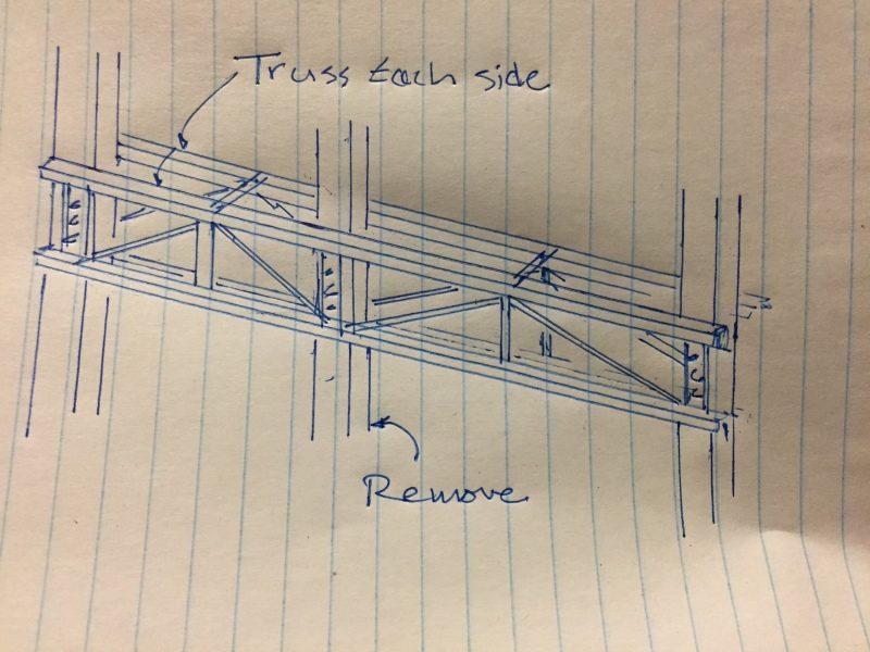
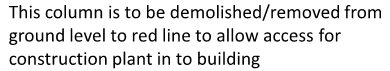
I would be interested to get peoples opinion on the design of a shear key around a column which receives the load from a transfer truss supporting part of a 14-storey building. Please could forum-users read this in conjunction with my attached sketch which is intended to convey alot of the information you might need to reply. I would like any discussion on this but am interested in failure mechanisms. I am especially interested in the my interpretation of the shear failure which I would appreciate comment on.

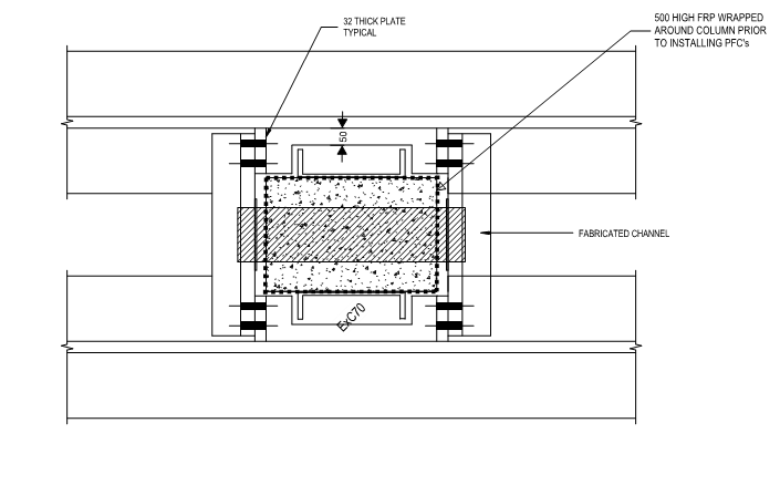
I would undertake a bearing check between the shear key and the concrete
- As there is a eccentricity between shear key and the applied load from the truss, Macalloy bars are to be used to provide equilibrium and they would be pre-loaded to maintain a clamping force and prove the installation.
- The shear failure would be a vertical shear failure akin to the maximum shear capacity achieved when designing a beam for web crushing at supports. Thus a significant shear strength can be mobilised in the concrete - in AS3600 this is approx 0.2*f'c*do*b where b is column width and do = height of column above shear key. The column would be able to mobilise this capacity above both shear keys.
- Steel design/stiffenrs/welded connections etc obviously required
- Bars to be preloaded to unfactored tension load.
- Load in column is approx 2000 kN dead and 250kN live (construction loading)
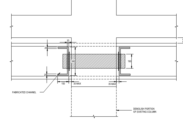
- I will probably use two shear keys stacked on top of each other to achieve safe bearing stress on to concrete which is driving design at the moment.

To ease peoples fears, my line manager has tasked me with producing a draft design for this, then he will check it thoroughly and is a very experienced engineer. I will not be designing this solely off of the back of advice on the forum but it will help me to understand the problem and thus present a sensible, worked solution to my manager for review.

Many thanks in advance.

Attachment link:
 
Replies continue below

Recommended for you

Something about relying on a 50mm key to transfer that much load doesn’t sit well with me. What’s the cover? Are you going to be close to cutting rebar? Personally I wouldn’t rely on the outer cover of a column to transfer that much.

Your sample building looks like there’s access to both sides of the columns. Is that the case for your project? If so you could sandwich the columns with trusses, something like in the attached.
3D22EFCB-D7AB-4AF0-8ECD-B5BC1D2B384C_jbmbiu.jpg
 
CANPRO, thanks for the reply.

With regards to the cover, it is 50mm (to the shear reinforcement). We will not being cutting any rebar.

There is access to both sides of the column but the connection between the truss and the concrete brings its own troubles - the anchorage required would be prohibitive i.e. size and number, I did look at this solution initially and discounted it. It required many large anchors, some of which would no doubt hit rebar.

I was too initially skeptical when I was shown this as a concept but it has been used successfully on one of my managers previous projects of which I saw photos of the finished install.
 
BAretired,

I took a look at the failure surface that you drew (thanks for that), could you explain what is happening there? how would you determine the depth that could be that you have drawn. With 2 shear keys in height I need approx 800mm to mobilise sufficient shear strength based on the shear web crushing strength given in the code (i.e shear strength = 0.2*f'c*b*d where b = width of column engaged by the shear key and d = 800mm). Have I mis-understood the failure mechanism here?

Thanks in advance.
 
Agree with CANPRO that I am a bit skeptical with the shear key. Would imagine something more robust is likely required.

1. Would suggest using a Pratt truss configuration with tension diagonals. You'll get a lighter truss.
2. You might want to consider the effect of the truss deflection on what happens after you cut the column. I have a feeling that you might have some significant deflection and produce cracking on the facade etc.
 
 http://files.engineering.com/getfile.aspx?folder=a6291dd2-74a0-46b5-bc13-70fcba94f92d&file=TRUSS.pdf
Pratt truss is good... also, I'd be securing a metal plate with a bearing support to the column to support the trusses. I'd locate the rebar to make sure I didn't core through them and I'd pressure fill using a flowable grout to ensure the through bolts were solidly bedded. I'd design the connection assuming the bolts took all the shear, and probably threads excluded. I'm not sure if I would recess the steel into the column. It may do something to the column and because of the difference in stiffness of the steel and concrete, it may cause the bearing to spall off anyway. For belt and suspenders support, you might consider using a structural adhesive between the plate and the column. Use plate washers with zero tolerance for the through bolts and weld them in place.

Provide adjustable shoring posts to support as much of the dead load as possible for the truss when the middle column is removed so that deflection is not sudden... I don't know how to support the shoring posts. Slowly retract them so the existing framing can 'adjust' to the new support conditions.

With any renovation work, where you are removing support, I'd advise the owner in writing that when you change a loading regime, that there can be unexpected movement and cracking as slickdeals notes

Dik
 
1) This makes me nervous too on a gut level. But, then, I long ago learned that I really can't trust my instincts when it comes to construction engineering. I'm too much of a coward by nature. If I trusted my instincts, nothing would ever get done. And, of course, your bosses example makes for one valid data point.

2) I believe that it's erroneous to be treating this as anything akin to conventional beam/truss shear. I don't anticipate any failure modes that would justify that kind of treatment. And I worry that taking web shear crushing strength over the entire height of the column below the shear keys will lead to a spuriously large capacity.

3) This bears considerable resemblance to the problem of steel column base plate shear lugs. In the US, we have AISC Design Guide #1 to give us some guidance with that. As one of my checks, I'd run this case against those procedures. The AISC method won't fully capture your problem though as the critical failure mode is often shear breakout of the concrete behind the key based on the available edge distance. Here, you've essentially got infinite edge distance. And that's great. We just have to search for something else meaningful to check her in order to establish capacity.

4) I also think that this problem resembles an anchorage problem far more than a beam shear problem. So I'd check that out a bit too. In the US, we'd use ACI appendix D provisions to evaluate that. No doubt you've got similar provisions in Australia as it's all based on the same euro-research anyhow. The failure mode that I feel would be most relevant here would be pryout. That mechanism keeps you from being able to mobilize extremely long lengths of concrete for resistance. Interestingly, your clever use of pretension to address eccentricity could also be used to deal with pryout which is also a result of system eccentricity. You'd just need to pay close attention to ensure that you're putting the pensioning where it needs to be vertically to do this job successfully.

5) How will you be prepping the shear key joints to ensure uniform key bearing against the column concrete? I have some ideas but I'd like to hear yours first.

6) This might be a good application for a post-tensioned truss if there's space. It would give you excellent movement control and would create a natural clamping action at the column supports.

7) One failure mode that I would investigate is the separation of a wedge of concrete below the shear key. They cover something similar in the PCA Concrete Handbook. Usually you're studying a case with an outwards horizontal thrust which makes thing worse. Without that thrust, I'm not even sure that it's possible to generate failure with this. I'd want to check it out anyhow though. Basically, you check shear friction on a bunch of possible failure planes to make sure than none are a problem. You use the bearing stress perpendicular to the assumed failure stress as clamping force, similar to if there was rebar there.

8) Another failure mode that worries me is creating a delamination failure of the concrete outside the column cage (also sketched below). It's probably paranoia but I'd either find a way to evaluate the potential for that or, more likely, I'd jacket the column with whalers or something for a few feet below the connection, until I was confident that the axial loads had spread into the column core sufficiently.

c01_h34lro.jpg


I like to debate structural engineering theory -- a lot. If I challenge you on something, know that I'm doing so because I respect your opinion enough to either change it or adopt it.
 
Delamination failure as mentioned in KootK's 8) above and shown in his sketch (b) is also one which worries me. It becomes more critical if the column is heavily reinforced. Jacketing the column may prevent buckling of the 2" wide strip, but the plane in contact with the reinforcement cage is weak.

I would prefer a solution where shear is carried by grouted through bolts rather than a shear key. This would entail X-ray of the column in order to locate reinforcement.

BA
 
BART... that's the way I'd do it... concerned about bearing on concrete outside the column reinforcing cage... Another issue... depending on where the column is located (at floor), there could be a significant number of rebars to locate, and another solution may be more appropriate...

Dik
 
Thank you all very much for taking time to reply.

Slickdeals – the building will be demolished to GL a month after cutting the column but I have designed the truss for a span/1000 deflection. Thanks for the sketch, I too would feel more confident with a through bolt solution but I have major concerns with taking so much of the section out when coring to insert the bolts. Have you ever done this before?

Dik – when you say ''because of the difference in stiffness of the steel and concrete, it may cause the bearing to spall off anyway'' do you mean that an even bearing between concrete and steel key may not be achieved and the edge of the chase may just spall and break off?. The support post makes sense, thanks for that.

KootK – 3) thanks for AISC design guide hint, I am sure there is similar guidance in Aus standards, ill look it up. 4) Yes this makes sense, I have done pry-out checks before, I can visualise this failure mechanism 5) to prep the shear key joint for uniform bearing, I planned to specify a chase in the concrete which is some 30mm taller than the shear key. Once the shear key was in place and packed up off of the bottom of the chase, shutter around the key with a letter-box shutter. Then pour high-strength grout in with a hand operated grout-pump from both sides until grout starts backing up and you know it is full. 7) Thanks, will investigate

With respect to the grouted/through-bolts option, would you not be concerned with pocketing lots of holes in the column? One benefit with the shear key is that apart from the chase, you leave the column intact.
 
If you do a finite element model with the steel and concrete, you will likely develop 'high?' tensile stresses at the junction of the steel and concrete.

How much is the l/1000?... if 1/2" then could also cause problems. You have to slowly release the load on to the truss.

Dik
 
almost 1/2"... make sure that any brittle elements are accommodated... and allow the deflection to occur over perhaps a week or so... nothing abrupt.

Dik
 
OP said:
With respect to the grouted/through-bolts option, would you not be concerned with pocketing lots of holes in the column?

It is a valid concern and it sounds as though that has informed your detailing thus far. Some things that you could do to address the concern while retaining a through bolted solution.

- array the bolts more vertically than horizontally so that you're sacrificing less section.

- use realistic loads and load factors for the temporary condition.

- use tested, in place concrete strengths.

- stagger bolt installation so that some cores are completed and epoxied before others are attempted. In this way, you remain mostly solid.

Through bolting is a weird part of the structural engineering dogma these days. To my knowledge, there is no accepted method for designing through bolts. Nor is there performance data to justify how in love we seem to be with that connection method despite that short coming. When I look at a through bolted connection here, I see:

1) Bolts that probably only engage the concrete meaningfully over maybe six bolt diameters which is mostly cover concrete.

2) A clamping force available across the column.

3) Possibly a fail safe mechanism where failed bolts could hang from the column core.

Your method also has #1 and 2 and probably does a much better job of both. It's lacks the redundancy of #3 though. I wonder of you could address that some other way. Maybe a single 2" pin through the whole thing or something.


I like to debate structural engineering theory -- a lot. If I challenge you on something, know that I'm doing so because I respect your opinion enough to either change it or adopt it.
 
Temporaryworks said:
the building will be demolished to GL a month after cutting the column but I have designed the truss for a span/1000 deflection.

dik said:
... make sure that any brittle elements are accommodated...

dik: Given that the building is going to be fully demolished soon after column load transfer, I assume the owner and OP are not too worried about brittle elements.

Temporaryworks: I looked at a project in AU back a few years ago where an existing hotel was modified and new steel transfer beams installed with several RC column demolished - 4.5m spans to create 9.0 m spans. To transfer load from column to transfer beams, the consultant used a 190mm dia solid steel pin installed through the existing RC columns (200 mm dia concrete core) then the annular space grouted up. Pin was welded to stiffened back-to-back channels, then bolted back to a pair of longitudinal steel plate girders. Some details:

Cross-section:​

Capturetransfer1_q3hfl8.png


Plan section:​

Capturetransfer2_tw8zj3.png
 
Kootk,

I find that an experienced engineers "gut instinct" is normally the best one to listen to, before any attempt to over analyse in order to justify accepting an other result. And mine has the same problem as yours on this one.
 
Ingenuity: Point taken... just a caution for the OP or anyone else that might undertake this type of renovation...

another thought: Why would anyone want to spend $100K to remove a column just to demolish the building afterwards?

Dik
 
I was wondering about that too. Must be some access requirement associated with the decommissioning/demolition of the original building. The time scale should be fun on this one. By New Year, OP should be able to tell us what he went with and how well it worked.

I like to debate structural engineering theory -- a lot. If I challenge you on something, know that I'm doing so because I respect your opinion enough to either change it or adopt it.
 
Status
Not open for further replies.
Back
Top