Continue to Site

Eng-Tips is the largest engineering community on the Internet

Intelligent Work Forums for Engineering Professionals

  • Congratulations waross on being selected by the Eng-Tips community for having the most helpful posts in the forums last week. Way to Go!

Shear load on bolts in built-up steel box girder due to Torsion

Status
Not open for further replies.

Dusni

Structural
Aug 7, 2016
10
Hi,

The member is a steel box shape consisting of (4) plates held together with an angle in each corner. Each angle leg has a single bolt every 6" along the member length.

I calculated the shear on the angle bolts in the direction parallel to the span due to vertical shear using VQ/It.

For shear on the bolts due to torsion on the member I'm not as confident...here's my calc. Am I missing something?
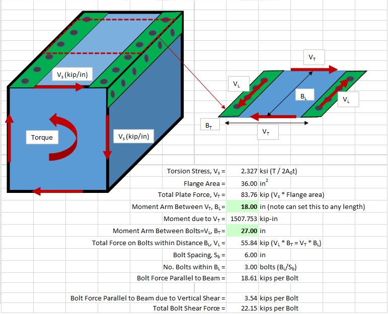
Torsion_s7yejk.jpg


Thanks!
 
Replies continue below

Recommended for you

1) I've been tripped up by this myself in the past. The torsion piece is almost too simple.

2) The method is this:

a) calculate the torsional stresses in your member walls.

b) multiply [a] by the wall thickness to get the shear flow resulting from torsion.

c) add [c] algebraically to the the flexural shear flows (VQ/I) to work out the aggregate shear demand on your connections.

3) FYI: I spent no time reviewing your spreadsheet and I'm generally only interested in the principles. And I'm lazy.
 
I'm with you on steps a) and b). And for c) I agree you'd just add the bolt shear due to flexure and due to torsion, since I think they both act parallel to the beam. For c) though how do you account for the bolt spacing?
 
What's bothering you about the bolt spacing? I'd think that you'd sum the sources of shear demand and assign each bolt a shear equal to that sum multiplied by the bolt spacing.
 
So for bolt shear due to flexural shear I did VQ/I to get shear flow in kip/in along the member then that x bolt spacing to get load per bolt. I can visualize that because the shear flow is per inch along the beam. For torsion though the shear flow is around the perimeter of the beam (although I guess there's also equal shear flow parallel to the beam??)

BTW I got the idea for my approach from this diagram you sketched out a couple years ago! Near the bottom:
 
Nice! Yeah, there is a complementary shear flow parallel to the member and that's what's kicking extra demand into your bolt line.
 
I suggest to read this article before proceed too far. Also note that the torsional shear is similar to the calculation of shear resistance using shear flow, so each face of the box beam will carry a torsional shear force of V[sub]s[/sub]*s, where "s" is the bolt spacing in the longitudinal direction of the box beam, and the shear is to be resisted by the bolts in the line of action. The bolt the shall be designed for the combined shears. Hope I haven't misunderstood your confusion.
 
Status
Not open for further replies.

Part and Inventory Search

Sponsor