Continue to Site

Eng-Tips is the largest engineering community on the Internet

Intelligent Work Forums for Engineering Professionals

  • Congratulations MintJulep on being selected by the Eng-Tips community for having the most helpful posts in the forums last week. Way to Go!

Shear Stress between Steel and Concrete

Status
Not open for further replies.

Arun4567777

Structural
Aug 11, 2020
87
Hi!

For composite beams as per AISC, the shear force that Shear studs are designed to resists is min of Steel Tensile Strength or Concrete Compressive Strength as given in Chapter I,AISC
My question is why we use Tesnile Strength or Compressive Strength as Shear force at the intrafe of two. What is the logic?
 
Replies continue below

Recommended for you

I don't think your statement is quite right. The following is the logic.

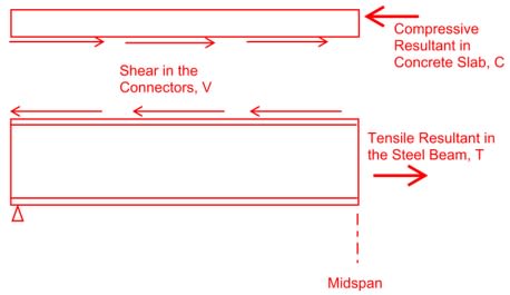
Draw a FBD of the beam and slab, exploded like below.

From sum of forces in the slab, C = V.
From sum of forces in the beam, T = V.
Thus, C = T = V. These three are always equal no matter what.

Mn is computed for the ultimate strength condition that occurs when the weakest of T, C, or V maxes out.

The max possible value of T is Tmax=Fy*As.
The max possible value of C is Cmax=0.85*f'c*Ac
The max possible value of V is the sum of the stud strengths, SumQn.

Thus, V = min(Tmax, Cmax, or SumQn). Figure out what that is and draw the unique plastic stress distribution that would cause it, sum moments around something to get Mn.

Composite_Beam_ynpjes.jpg
 
Thanks for the reply. If I subject a composite beam to pure bending. The Shear force would be zero. Eg. If I stack 6 planks together and apply pure bending on them, the planks won't slip. If I apply bending and Shear, the Shear forces would cause the planks to slip. Following the same logic, the C and T force generates a moment resistance foe the beam. The actual Shear force in the beam or max shear capacity of beam should be used to calculate the stud force.
 
In a Plate Girder with Flange and Web, we design the weld between Flange and Web for the actual shear Force. Following the same logic, the same shear exists between the interface of concrte and steel. I hope I am making sense.
 
Study the FBD and logic I typed above. It is the situation for a typical composite beam. It might help to try not to think so much about what you learned in Mechanics of Materials class. All that stuff was formulated for linearly elastic. In this case, you're trying to figure out what would be going on at the ultimate strength. That FBD and simple statics stuff I typed above are what you need to be thinking about if you want to understand the logic for this.

You mentioned "pure bending." Sometimes beams have segments with pure bending and no shear. For example, a girder with two equally spaced point loads. In that case, the figure I drew above would need to be slightly altered by replacing "midspan" with "1/3 point."
 
Thanks!
I have one more question. I designed a composite beam with 250 mm slab on top. The contractor casted 150mm only and now again he will cast the remaining 100 mm. There will be a horizontal joint. Is their any way we can still get composite action for 250 mm
 
Presumably, the concrete stress block is contained in the top 100 mm. You would need to show that there's enough shear-friction strength to transfer the resultant of the stress block across the concrete-to-concrete interface. This is the first time I've heard of such a situation. I would think you'd need vertical rebar crossing that joint to allow for a shear-friction calculation. There's not much room to develop the rebar, though. Maybe there's some other approach, but none comes to mind.
 
Status
Not open for further replies.

Part and Inventory Search

Sponsor