somebodyfromworld
Mechanical
- Jul 15, 2015
- 35
Hi there
I've got a task where i need to use manual calculations with this setup (see attach.)
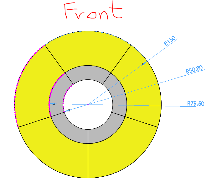
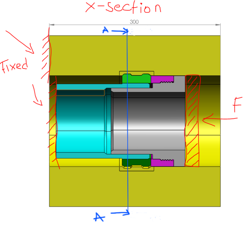
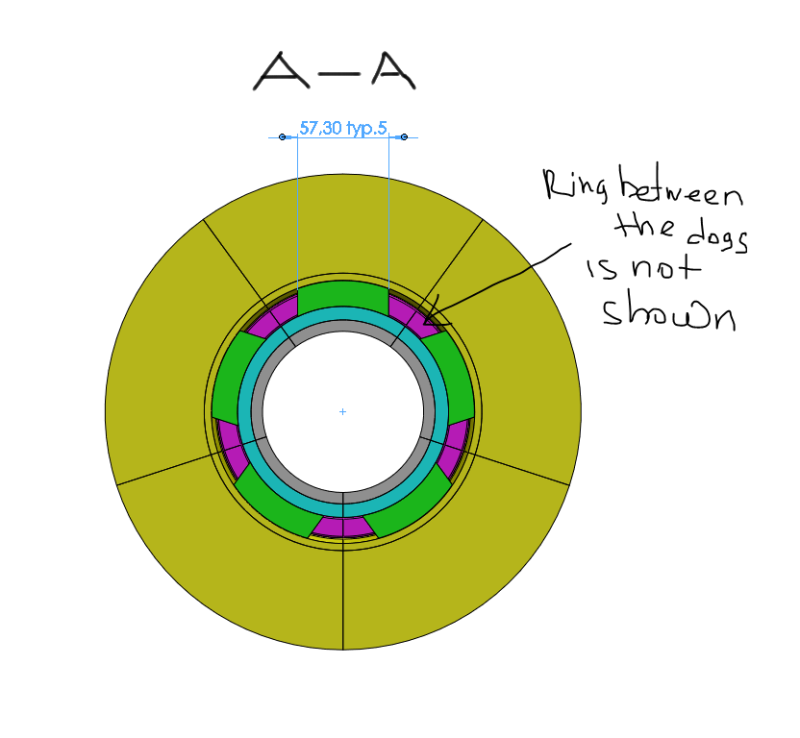
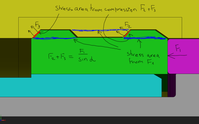
there is a cylinder with two internal grooves (yellow part). 5 Dogs are equally spaced (72deg.) inside that cylinder. They are being pushed by the Force against the grooves in the cylinder. What stresses i have to calculate to make sure the construction is stable with applied Force. And what equations I need to use.
Kind Regards, S.
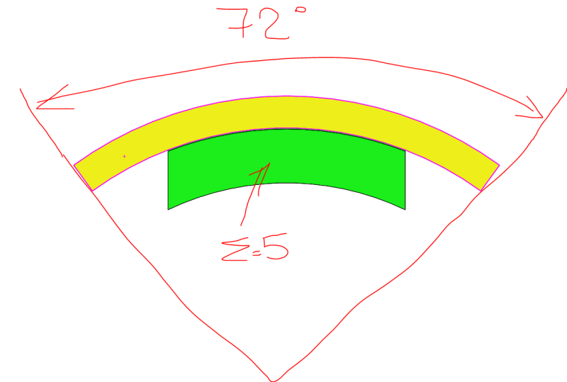
I've got a task where i need to use manual calculations with this setup (see attach.)
there is a cylinder with two internal grooves (yellow part). 5 Dogs are equally spaced (72deg.) inside that cylinder. They are being pushed by the Force against the grooves in the cylinder. What stresses i have to calculate to make sure the construction is stable with applied Force. And what equations I need to use.
Kind Regards, S.


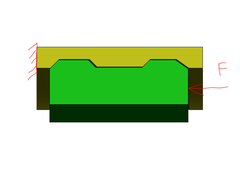
![[smile]](/data/assets/smilies/smile.gif "[smile] [smile]") . I just wanted to confirm what I'm going to calculate is correct. Here is more detailed screen shots. Am I right with the last screen shot?
. I just wanted to confirm what I'm going to calculate is correct. Here is more detailed screen shots. Am I right with the last screen shot?