Eng-Tips is the largest engineering community on the Internet

Intelligent Work Forums for Engineering Professionals

  • Congratulations waross on being selected by the Tek-Tips community for having the most helpful posts in the forums last week. Way to Go!

Shear walls on small three seasons room addition w/ all windows

Status
Not open for further replies.

mfstructural

Structural
Feb 1, 2009
225
0
0
US
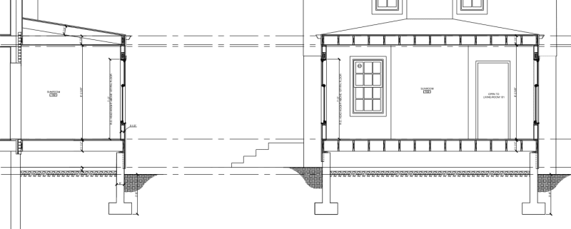
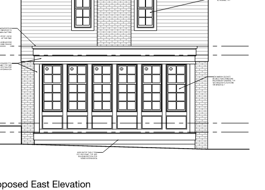
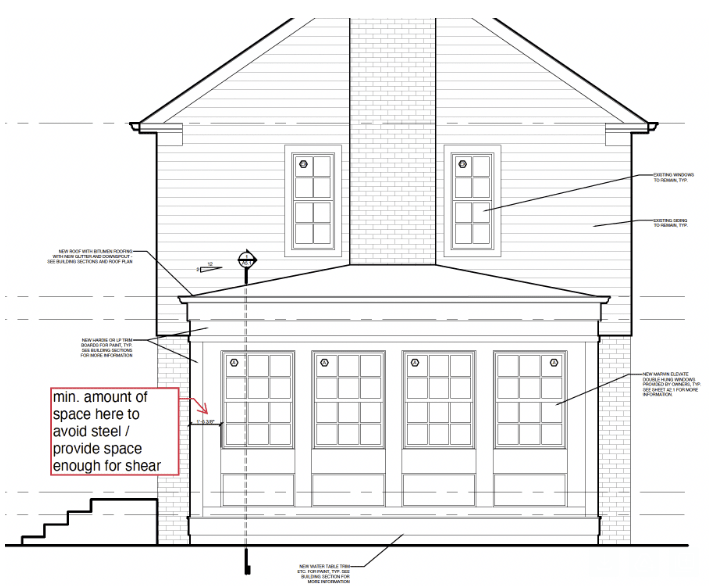
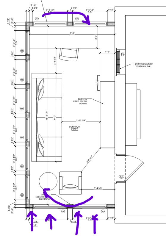
I'm designed a small three seasons room addition to a house and had a question regarding shear walls. The addition is 20'x9'x9'(H), see attached files. There are windows around the perimeter of the room. At first I was thinking of running headers below and over the windows(between the posts, so having posts go from foundation to underside of roof, so there would be a double 2x at top of the wall as well) and using a Simpson corner post cap to provide rigidity at the corners. If it's a rigid structure I was thinking it would want to rotate like a couple (see last image attached). For wind load of 20psf this is a T=C=(20psf*9'*4.5'(H))/20'=40 lbs. Does this seem like a reasonable approach? for a 40 pound load, some lags or anchors between the addition and existing structure will be adequate.

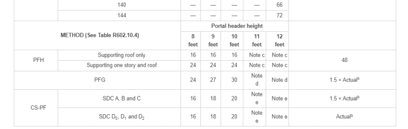
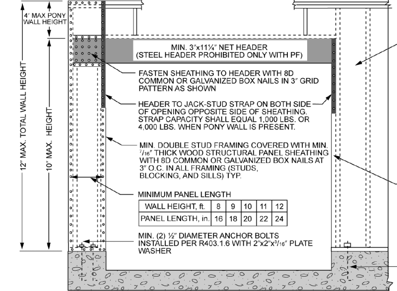
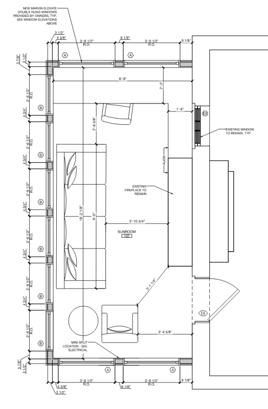
The other option is to provide a shear wall or steel frame at the 20' long wall. The architect is asking what is the minimum length of wall we need at the corners for shear. Right now it's approximately 1'-5" from corner to window. I have not run any numbers but there are many windows. From a practical standpoint, there is a similar three seasons room there now with all windows with no evidence of movement.

Just trying to figure out the best most economical way to approach this.

Thanks,

eng_tips1_kvxlsj.png

eng_tips2_orsbmv.png

eng_tips3_hiwgce.png

eng_tips4_ixywye.png

eng_tips5_ndqznq.png
 
Replies continue below

Recommended for you

You can get vertical support from some posts, but the lateral system isn't there. If you can get the roof to work as a (rigid) diaphragm and tie into the existing structure enough, that's maybe workable. This is a cantilever diaphragm in that scenario. Think of it more like a glorified deck that's got sails between the posts (the windows catching the wind).

For wind up/down, you'd get a moment due to the centroid of the wind load versus the "one wall" of resistance (that 20' wall shared with the existing structure, [do you really have 20' of wall there with a fireplace going through it?]), and a couple due to the eccentricity of the wind load versus the up/down shear wall (ten feet, roughly), that couple has to be resolved with connections into the existing building at the upper/lower walls which go into a floor system in the existing house.
 
So the best approach here is to just have a steel moment frame and have the joists sit on that and everything tied together at the top. I didn't check the shear walls yet, but 1'5" long x 9' high sheathed walls likely aren't adequate even though lateral loading is relatively small.
 
I would look at portal framing per the IRC.
You need a 16" minimum panel for an 8 ft. wall (18" for a 9 ft. wall)
If it wasn't for that big ass chimney, I'd be tempted to just use the roof connection to the house to provide the lateral stability.
 
My first pass with these types of situations is to do as lexpatrie indicates, treating the roof diaphragm as a rigid cantilever providing tension ties back into the floor system. Sometimes that gets tricky with any steps between roof to floor, but it looks like you got a good opportunity to tie into the second floor here. My guess is that all shear could be transferred at either side of the chimney. These solutions feel much more reasonable when the numbers work than proposing steel moment frames.
 
I'm looking at Table R602.10.5 of 2018 IRC and see the portal header height is 18" for a 9' wall height, for a continuously sheathed portal frame. Idk if I'm interpreting this table correctly but where is it showing the minimum panel length?

eng_tips_6_ccrorl.png
 
The header height is distance to the top of the header. 18" is the panel width (as was stated in my previous post)
Our table (NC) does not look like that.

pf_dtvzkw.png


Also consider what Flotsam said.
 
SWComposites - oh, they're supposed to. Generally, those 'kits' are meant to infill below a covered patio or raised floor. Just because the plan reviewer doesn't recognize that they are triggering a structural review and likely reinforcement doesn't mean it's not supposed to happen.

I can buy a kit for a 2,000sf steel shed on the internet and erect it myself. Doesn't exempt me from zoning and building permitting regs.
 
In this case, it's a four seasons room sorry. There is an existing three seasons room replacing with four seasons room and they want to potentially add a second story addition at some point. i forgot to mention that, thanks for reminding me.
 
As others have already said, I would try to design it will the roof diaphragm taking all the wind load. You'll need to ensure that the diaphragm can transfer shear into the exterior wall of the house and also that the compression and tension (hold-down) couple perpendicular to the wall is resisted. Due to the geometry of the addition, I think you should have no trouble making this work. The loads are small, as you already know.

For shear resistance at the outside wall, I have occasionally used columns which would go from foundation to top of window, with there being a beam below the windows tying them together laterally. So the column essentially cantilevers for the height of the window. I wouldn't do that here, though. The roof diaphragm approach is better IMO.

SWComposites said:
so out of curiosity, why does a "three season room" need to be engineered to same level as the house, when one can buy them from places like this, that don't seem to be designed to the same level of requirements?
I happen to have a builder friend who installs these. He told me that they're all engineered/stamped. I don't doubt him, but looking at some of them, I do wonder how they manage to meet code. The structure always seems so minimal.
 
A lot of them are aluminum, so they can get some actual moment connections.

If they want to add a second floor, use shear walls. Whether it's a wood portal frame (look up portal frame for engineered applications from APA) or simpson strong walls.
 
Don't forget to check the uplift on the corners. The IRC requires these minimum width sections of walls at corners for not only lateral stability but also for an empirical uplift capacity.
Lots of wind pressure pulling up at the corners. May need strapping to resist that.

 
lexpatrie said:
If you can get the roof to work as a (rigid) diaphragm
When you say get it to work as a rigid diaphragm, what exactly are you referring to? I'm imagining a shear wall on it's side.

1. Resolve all required shear into the diaphragm.
2. Design the chords for the diaphragm. Essentially the headers will be acting as compression/tension collectors, delivering all loads to the existing building.
3. What checks have to be done in regarding to diaphragm flexibility?
4. Is a sub diaphragm needed to introduce the windward/leeward loads from the wall into said rigid diaphragm?
 
phamENG - I have used the same technique for 2-story applications treating both diaphragms as cantilevers and tying them into the roof/floor. I've only done this for relatively small additions, at a certain point, conceivably when the diaphragm no longer satisfies the rigid diaphragm check in SDPWS 4.2.5, you'd need a VLFR element on the front edge - prior to that I don't see a problem with it. The aspect ratio of this addition lends itself to this solution quite nicely given the small projected area and large moment arm between the chords.

I do go through the effort of detailing a transfer diaphragm at the main building Terry Malone style when using this system, one or two story.
 
StrEng007 - wood diaphragms are typically assumed to be flexible, so the lateral load is sent to vertical LFRS elements (shear walls) according to their tributary area - not based on stiffness.

In this situation, that assumption doesn't work. So you do essentially as you said - think of it as a horizontal shear wall. Then you check the drift to see if it's acceptable. There is no code mandated drift limit for wind. "Typical" practice is usually to use 10 year MRI wind loads with a limit of H/500. Some go as low as H/360 (PEMBs do H/60 if you don't stop them), some will insist on H/600. I believe there's also a hard 3/8" where drywall will start to crack, but don't quote me on that number. I think it's in ASCE 7's serviceability appendix or the commentary.

Diaphragm chords are usually the top plate of the wall as it is supposed to be continuous.

If you're doing a rigorous diaphragm analysis, yes - you need sub diaphragms due to the fireplace breaking it up.

To the OP: here's a nice wrinkle for you. If you use the existing structure, you're likely increasing the in-plane wind load on that wall more than the threshold permitted by the code to ignore the effects. That means evaluating the existing construction for modern wind codes. From my experience, that never ends well. Hopefully you're removing the brick veneer on the exterior face of that wall and can reinforce it.

 
Flotsam - how much retrofitting do you end up doing to the existing structure? Adding a single floor can often be justified globally with minor, localized retrofitting...but adding two floors? I'd start to get concerned about more of the load path. I like to make these self supporting whenever possible, and only use the cantilevered diaphragm as a last resort. People usually get surprised when you start calling out interior reinforcement for an addition they thought would be outside the existing building footprint.
 
phamEng - it definitely depends on the project. I'm only going to do the cantilever diaphragm if the client accepts the details required to do so, including removing interior finishes and creating the collectors into the transfer diaphragm - perhaps reinforcing existing shear walls and adding hold-downs as well. For the two-story ones I've done there was also substantial renovations in the main house, so adding those details was no problem and much preferred over a moment frame which is often the only other option when dealing with situations like the OP's where there's not even enough room for a strong-wall. I've pondered doing the cantilever column idea Eng16080 mentioned but haven't had to go down that road yet.
 
I don't say this very often and am perhaps out of line or missing something, but some of the solutions mentioned above seem way overkill based on the magnitude of the actual loads. My understanding is that there's a total 800 lb shear force which needs to be transferred into the existing exterior wall, and 40 lb tension and compression forces at the front and back (diaphragm chord locations). Assuming the extra 800 lbs doesn't overload the existing wall, I don't see any of this as being difficult to accomplish or requiring special detailing outside the norm. I would use a continuous ledger connected to the existing wall with diaphragm nailing into the ledger. I'd probably just ignore the 40 lb forces. Where the ledger can't be connected to anything structural, it will act as a collector. As long as you have at least a couple feet where the ledger is attached to something structural, I think you'll be fine.

Or, use the cantilevered column approach, in which case you only need to resist 400 lbs at the outside wall. Seems very doable with 2 or more of those.

Let me know if I'm missing something.

 
Agreed that some of the details I mention are overkill in certain situations, possibly this one. At a minimum I'm going to provide a DTT or something similar at the chords to tie into the main building, like you would for a deck, where even there we don't rely on the ledger fasteners to transfer any tension though in reality there obviously is some unreliable amount of capacity to do so.
 
Status
Not open for further replies.
Back
Top