Continue to Site

Eng-Tips is the largest engineering community on the Internet

Intelligent Work Forums for Engineering Professionals

  • Congratulations The Obturator on being selected by the Eng-Tips community for having the most helpful posts in the forums last week. Way to Go!

Sheath Standing Voltage at Fault Condition of HV 69kV cu / XLPE Cable 6

Status
Not open for further replies.

leur2011

Electrical
Jan 20, 2012
54
Our 69kV underground direct buried cables installation is having a single point bonding system, 3 x 1core-1000MCM cu/XLPE/CuW/Lead/HDPE per phase laid in trefoil formation with associated 1 x 1core - 4/0 cu AWG ground continuity conductor per phase for a span of 2 kilometers, link box with sheath voltage limiter (SVL) is provided at the mid-point of the circuit (1000m). Solidly grounded at both ends.

The cable manufacturer induced voltage calculation at normal condition indicates 0.02 V/m at load current 371 A. During fault conditions we consider 40 kA short circuit fault current. The sheath standing voltage for 3-phase fault is 1.24 V/m which is below our tolerable 5 kVrms, but for single phase to ground fault the manufacturer consider 40 kA fault current and the result is 11.2 V/m that is 11.2 kV at mid-point.

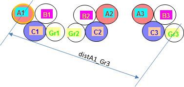
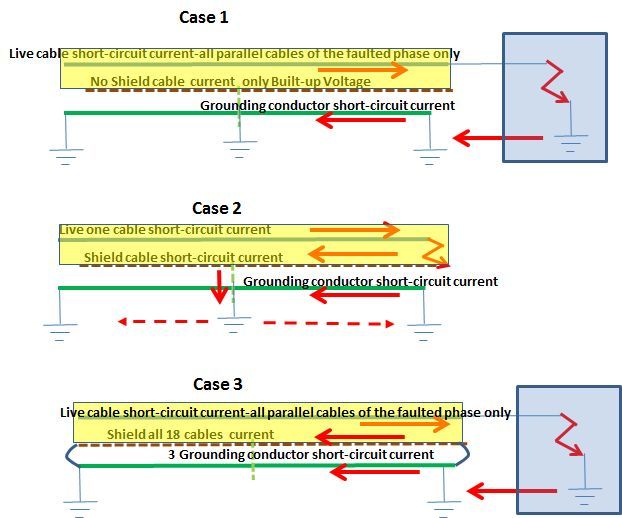
My question: In case of single point bonding system, having 3 cables per phase (trefoil formation), and where system is operated in abnormal condition with only one cable per phase; do we need that the sheath voltage calculation shall take into account the division of any ground fault return current between the three ground continuity conductors?
 
Replies continue below

Recommended for you

Does anyone see my post? Looks like it was locked since I edited the specification of 69kV cable in my OP.

Thanks
 
At first, it is something confusing. You say:
"is having a single point bonding system" and also :"Solidly grounded at both ends."
I think you meant the grounding conductor is solidly grounded at both ends.
If all three grounding wires are bonded together at both ends, the return short-circuit current will flow
through all. The current will be shared according to mutual reactance between live, shield and grounding conductors. In my opinion, you may consider the grounding wire as a forth phase.
The mutual reactance it may be k*ln(1/disti,j) where disti,j=the distance between conductor i and j.
For instance between the shield of cable R1[ or A1] from the first group and the grounding wire of the third group Gr3[center-to-center].
Short_circuit_current_shared_between_grounds_unaggo.jpg
 
7anoter4

Thanks for your quick response. You are correct, the ground continuity conductor per phase are bonded together and solidly grounded at both ends. The image you posted is the exact configuration of our cables.

1) We also group bond the metallic shield/sheath of each single conductors in the termination points and connect to the local ground grid via ground wire conductor, is this safe?

2) In case of single conductor (say phase A1) to ground fault within the Phase (A1, B1, C1) of close trefoil formation, what should be the fault current we are going to consider to calculate the induce voltage (sheath voltage gradient) at fault condition; 40kA or 40kA / 3 = 13.33kA?
 
Cable_Shield_Grounding_at_middle_distance_yhwtj2.jpg

1) In my opinion, using the grounding return wire as shield grounding will add a new voltage drop in the loop so the result could be more than allowable. I should ground the shield directly to a grounding electrode.
2) I think the short-circuit 40 kA it has to be rated per phase. However, the current is shared between parallel cables according to mutual reactance as I said.
 
Appreciate if you can demonstrate the calculation formula of Mutual Reactance for single conductor to ground fault in trefoil formation as shown in the image you've posted to verify if the short circuit current will be divided into three cable hence the max. short circuit current which carried by the cable metallic sheath will not higher than 40kA/3 = 13.3 kA at any condition.

Correct me if I am wrong, for through fault conditions( fault external to the cables) , phase to earth fault , the fault current will be returning through the three of the ground continuity cables and the cable sheath. The fault level in such condition will be 40kA/3.

For any fault within the cable , the cable and the sheath shall withstand 40kA for 1 sec.
 
In my opinion, if the shield is grounded only in one point-in the middle distance-only a small capacity current will flow through it-and it could be neglected.
On the other hand, if the cables are arranged as in above sketch, a symmetrical distribution of the currents is expected, indeed. So, in my opinion, each live conductor and grounding conductor will carry 1/3 phase current.

 
So, you assumed that if the metallic shield (screen) and lead sheath of the 69kV cable is grounded at mid point via link box with sheath voltage limiter (SVL), the fault current will be divided through the phase live cables + ground continuity conductor, but I am asking for the shield/sheath if the fault current will be completely pass through the cable shield/sheath so you have to consider 40 kA instead of 13.3 kA in the sketches you've posted or the fault current will be divided so that the fault current will not be higher than 13.3 kA at any condition?

I just want to understand what’s the difference between the fault external to the cable and within the cable , it is all about the short circuit current value pass through the shield/sheath?
 
Since the shields and sheathes are not bonded intentionally together we presume the shield grounded both sides it would be accidentally, so only one shield would be involved. The shield impedance will be Rsh+jXsh=~0.15 +j0.23 ohm/2000 m[0.27 ohm impedance] and grounding wires -3 of 4/0 copper parallel- will be 0.11+j0.23 [0.25 ohm impedance] .
In my opinion, one shield -and parallel lead sheath- impedance presents the same impedance as all three grounding wires together. Then the return current will split equally in the shield with sheath and grounding wires-about 20 kA.

 
With reference to your post as "For one shield -and parallel lead sheath- impedance presents the same impedance as all three grounding wires together. Then the return current will split equally in the shield with sheath and grounding wires-about 20 kA.", just wanted to know the values of impedances (e.g. positive, negative, and zero sequence) you've used to arrive for the return current will split equally in the shield with sheath and grounding wires-about 20 kA?

My calculation for positive and negative sequence impedance per kilometer is shown on the link:
[URL unfurl="true"]https://res.cloudinary.com/engineering-com/image/upload/v1449861373/tips/P_N_Impedance_wqxqjr.pdf[/url]

And the zero sequence impedance calculation per kilometer is shown on the link:
[URL unfurl="true"]https://res.cloudinary.com/engineering-com/image/upload/v1449861522/tips/Z_Impedaance_xz8poz.pdf[/url]

Well, I have also noticed that your calculation for impedances of one shield is for 2 kilometer. And that the shields and sheathes are not bonded intentionally together we presume the shield grounded both sides it would be accidentally.
 
In my opinion, this formula is for three phase cable conductors. Here is about one cable shield parallel with lead sheath against 3 grounding wires grounded at both ends only.
For copper tape and lead sheath you don’t need skin effect but for grounding wire you do.
The reactance is due to common magnetic flux entering the loop-of the shield and of the grounding
wires.
The copper shield resistance at 70 degrees C [275 mm^2 as per manufacturer catalogue for 40 kA 1 sec.]= 1/58/275*2000*(234.5+70)/(234.5+20)=0.15 ohm
The lead sheath of 0.2 mm thick 60 mm diameter [60*pi*0.2). Rlead=1/4.67/37.7*2000*(1+0.0393*(70-20))=33.68 ohm. Common resistance R1=0.15*33.68/(0.15+33.68)=0.149 ohm.
The loop reactance of shield+sheath and 3 grounding cables is:
X=2*w/10^4*ln(2*av.dist/shield dia)*length[km] w=2*pi*60
av.dist=(dist.A1_Gr2*dist.A 1_Gr3*dist.A1_Gr3)(1/3)=208 mm [measured on sketch- approx.]
X=0.2924 ohm
In this case Zsh=sqrt(0.149^2+0.2924^2)= 0.3277 ohm
Rgr=0.118 ohm [20 oC,skin effect, 3 conductors parallel]
Zgr=sqrt(0.118^2+0.2924^2)=0.3153 ohm.
 
My calculation for induced voltage at normal condition using IEEE Std 575 Annex E Is shown on the link:
[URL unfurl="true"]https://res.cloudinary.com/engineering-com/image/upload/v1449897633/tips/Induced_Voltage_Calc_at_Normal_Condition_eh64nv.pdf[/url]

And at 3-phase fault, phase-to-phase fault, and single conductor to ground fault condition, is shown on the link: With the assumption that the 40000 amps fault current (40kA/3 = 13.33kA) is shared by 3 parallel ground continuity conductor.
[URL unfurl="true"]https://res.cloudinary.com/engineering-com/image/upload/v1449897648/tips/Induced_Voltage_Calc_at_Fault_Condition_tfrj62.pdf[/url]

My question is: Base on your given parameters in your post on 11 Dec 15 21:42, and one shield -and parallel lead sheath- impedance presents the same impedance as all three grounding wires together. Then the return current will split equally in the shield with sheath and grounding wires-about 20 kA, what have you got for induced voltage at fault condition?
 
First of all, I have not the last edition of IEEE 575 with me. In my edition [1988] Appendix D, D2 Voltage Gradients Induced in the Cable Sheath:
“The voltage gradient induced in a cable sheath may be considered as a special case in which the conductor that it embraces equal to the mean radius of the sheath. When no other current carrying conductor is in the vicinity, the three sheath voltage gradients for a group of cables in any formation carrying balanced three-phase conductor currents are then given by:” See also:
D2.2 Trefoil Formation Single Circuit. D2.4 Double-Circuit Systems.
Entire Appendix D treats the three phase steady load -or short-circuit case -in which there are balanced three phase currents. You case it is for single phase-to-ground fault.
If you'll treat this as symmetrical components you'll get 1/3 of ground fault current in each phase but this it is not actually-it is a virtual current introduced in order to facilitate the calculation. The actual current flowing through the live faulted conductor it is the entire single phase to ground fault current and no current will flow through the other conductors.

 
Considering a phase to phase to ground fault; For a through fault most of the fault current will be carried by the phase conductors.
Current in the grounding conductors will be the result of impedance unbalances between the phases and triplen harmonics.
With a single phase to ground fault the fault current will return via the grounding condustors. This may form a voltage divider with a sheath voltage above ground close to the fault of over half of the phase to ground voltage.
If the source is less than infinite, the sheath voltage will be reduced due to the source voltage drop. (The impedance of the phase conductors is less than the impedance of the grounding conductors.)
However, the actual sheath voltage above ground in the event of a single phase to ground fault may be many times the calculated voltage due to induction.


Bill
--------------------
"Why not the best?"
Jimmy Carter
 
Thanks waross, you've raised one of the concern that I would like to find out with the issue of induced sheath voltage at fault condition when you said "the actual sheath voltage above ground in the event of a single phase to ground fault may be many times the calculated voltage due to induction."

Your statement is actually found in IEEE Std 575-2014 para E.1.3.3 single-phase ground fault (solidly grounded neutral) which states that "Precise calculation of shield/sheath overvoltages for underground-fault conditions requires a knowledge of the proportion of the return current that flows in the ground itself and the proportion that returns by way of the parallel GCC. This depends on a number of factors, which are not usually accurately known. Fortunately, however, the overvoltages of practical interest are those between shields/sheaths and the parallel GCC, and these can be simply calculated by the assumption that this conductor carries the whole of the return current. This assumption is normally accurate and leads to shield/sheath overvoltages that are slightly higher than those observed in practice."

Per 7anoter4 point of view, if all three grounding wires are bonded together at both ends, the return short-circuit current will flow through all. The current will be shared according to mutual reactance between single conductor, shield/sheath and grounding conductors.

Do we have mathematical representations to demonstrate the return fault current are actually not equally divided between live conductor shield/sheath, and ground continuity conductor during a single conductor to ground fault?
 
The point is that induced sheath voltages are one thing. With a phase to phase fault, most of the current returns via the phase conductors and the induction calculations based on the current are valid.
An I2R drop from a voltage divider circuit is entirely different.
With a single phase to ground fault where the current is returning through the ground conductor results in a large I2R drop in the ground conductors.
If you concentrate on the induced voltage and ignore the I2R voltage resulting from the ground current in the grounding conductor you may someday be facing a due diligence issue in front of a coroner's jury.

Bill
--------------------
"Why not the best?"
Jimmy Carter
 
Our cable design is:

- For the ampacity, the total load for each phase shall be 1112 A and each 1core x 1000MCM will carry 371 Amps since the phase contains three cables in trefoil formation. The source is a 3-winding autotransformer; rated at 133 MVA 69kV secondary, solidly grounded neutral; feeding 69kV gas insulated switchgear (GIS). Applying derating factors, the lowest calculated single conductor ampacity is 444 Amps, still higher than the anticipated 371 Amps.

- Each cross section of single conductor CuW shield / lead sheath in case of short circuit is capable to withstand 40 kA for 1 second.

- Each 4/0 AWG ground continuity conductor is calculated to carry 40 kA. We have 1 GCC per phase. Total 3 parallel GCC.

So, I am more concern with the induced sheath voltage at fault condition; single conductor to ground fault, to my opinion poses safety issues with the selected type of single end (point) bonding at mid point within a span of 2 kilometer as mentioned in my first post.

 
I am sorry, leur 2011.In my opinion, you have to decide, at first, what case of fault you want to study:
Case 1.Conductor phase-to-ground fault cable outside. All shields and sheaths grounded in the middle only. The short-circuit current returns through grounding wires and earth.
Case 2.Conductor phase-to-ground fault inside one cable. Short-circuit current returns to source through this cable shield also.
Case 3.Conductor phase-to-ground fault cable outside. Cable shields grounded both sides.
Case 4. Other possible case.
 
I don't know if I understand correctly what warross want to emphasize when he cited that "An I2R drop from a voltage divider circuit is entirely different" for a single phase to ground fault where the current is returning through the ground conductor results in a large I2R drop in the ground conductors.

- Maybe, because the conductor currents tend to induce currents in parallel metallic paths – including the cable sheath?
- Allowing these sheath currents to flow generates losses that can reduce ampacity 30-40%

7anoter4, the Case 1 and Case 2 are more applicable to our cable configuration. However, could you please explain the difference of fault outside and inside the cable;

- Case 1. Conductor phase-to-ground fault cable outside
- Case 2. Conductor phase-to-ground fault inside one cable

 
3_CASES_OF_SHORT-CIRCUIT_bhwqim.jpg

Case 1.
The short circuit point is located in the supplied equipment-or installation.
"the fault external to the cable".
The short-circuit current flows in all 3 parallel live cables of the faulted phase.
Shields grounded at middle distance only.
No current flows in the shields.
The short-circuit current flows in all 3 parallel grounding cables.
Case 2.
when one cable- of three per phase- insulation breaks down in one point and the sheath or shield will be grounded in one more point-that means inside the cable.
The short-circuit current flows in a part of the shield up to the grounding connection point- only in the faulted cable.
Case 3.
The short circuit point is located in the supplied equipment-or installation.
"the fault external to the cable".
The short-circuit current flows in all 3 parallel live cables of the faulted phase.
Shields grounded at both ends.
The return short-circuit current flows through all 18 shields in parallel with the 3 grounding conductors.
 
Status
Not open for further replies.

Part and Inventory Search

Sponsor