Eng-Tips is the largest engineering community on the Internet

Intelligent Work Forums for Engineering Professionals

  • Congratulations waross on being selected by the Tek-Tips community for having the most helpful posts in the forums last week. Way to Go!

SHEET METAL BENDING - CAPABILITY OF MANUFACTURING

Status
Not open for further replies.

elinah34

Mechanical
Aug 19, 2014
115
0
0
IL
Hello,

I would like to please check how difficult might be the manufacture of the suggested design below.

I am sure there are more options of manufacturing this, but I am interested to know if the suggested design is OK.

Here is a picture of the stainless steel 304L or 316L (both possible) 2.5 mm bended box, while dimensions are in [mm]:
1_0001_jnln8n.jpg


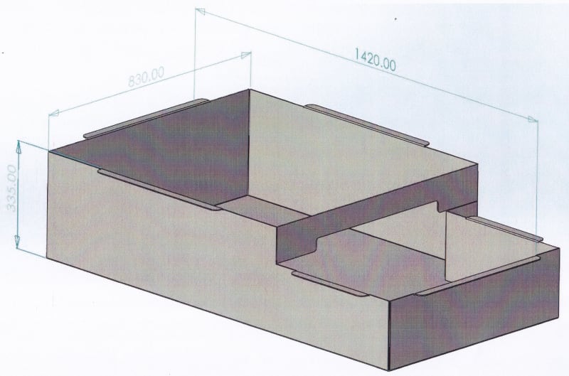
The design intent is creating this with minimum weldment lines.


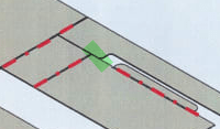
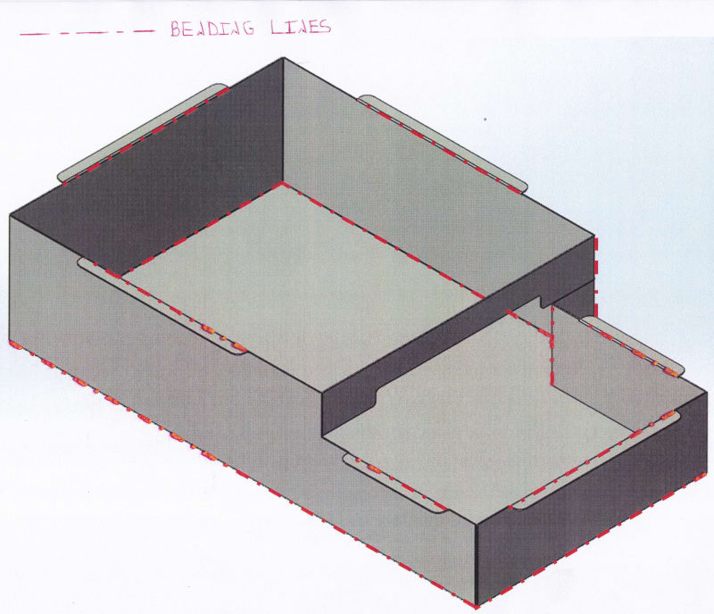
Here is a picture of the box with the bended lines marked on it with red dashed lines:
2_vj5ymv.jpg


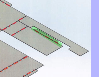
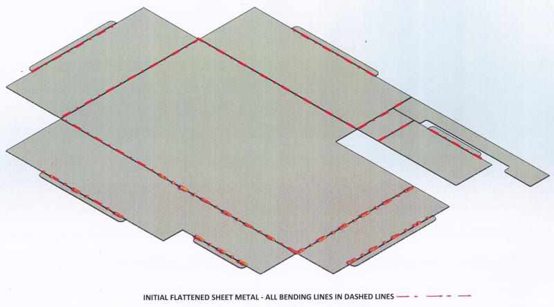
Here is a flattened configuration of this box while the bended lines are marked with red dashed lines:
3_jp80ad.jpg


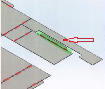
Now I am going to present the (mine) suggested steps for creating this box.
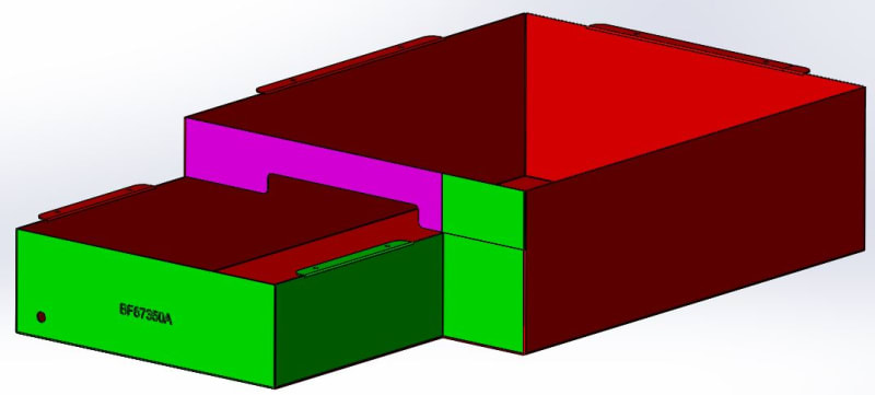
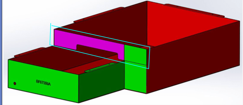
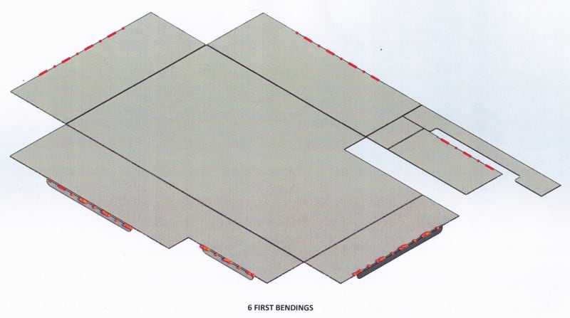
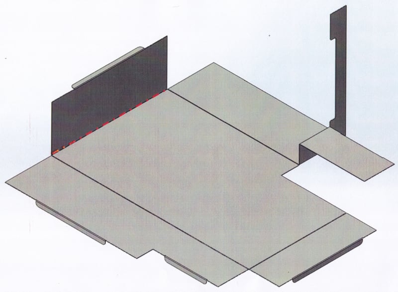
1st step - bending these lines:
4_zdba5o.jpg


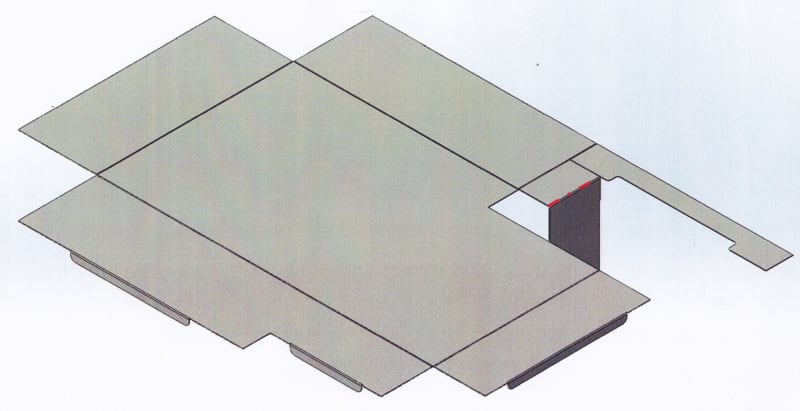
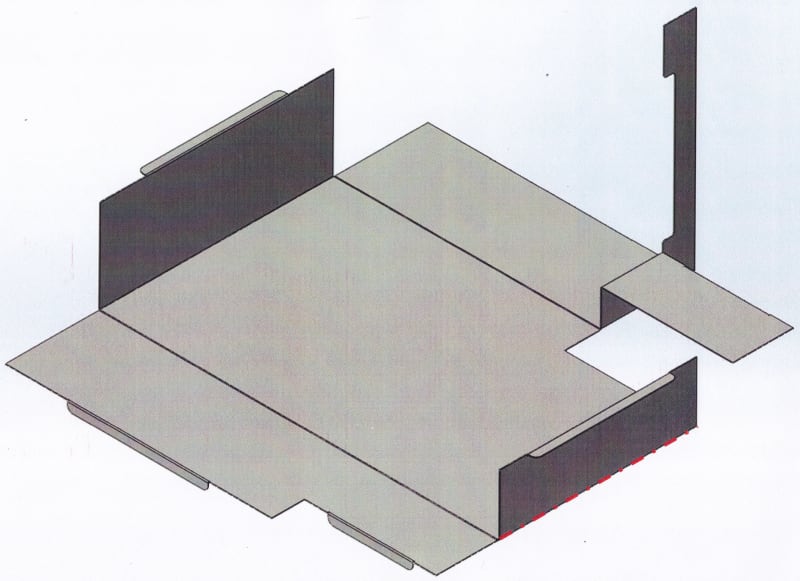
2nd step - bending this line:
5_0001_w4bvdg.jpg


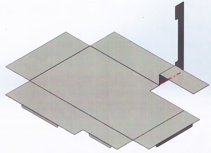
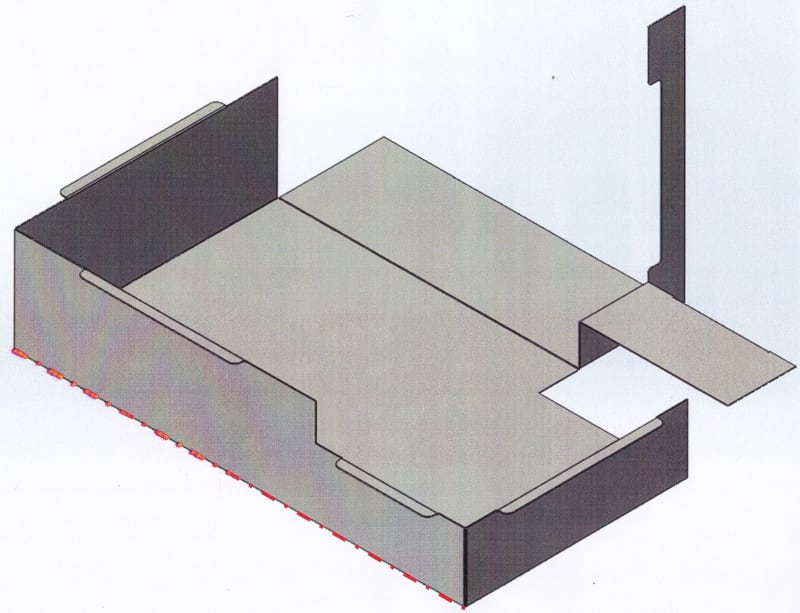
3rd step - bending these lines:
6_o2dgz3.jpg


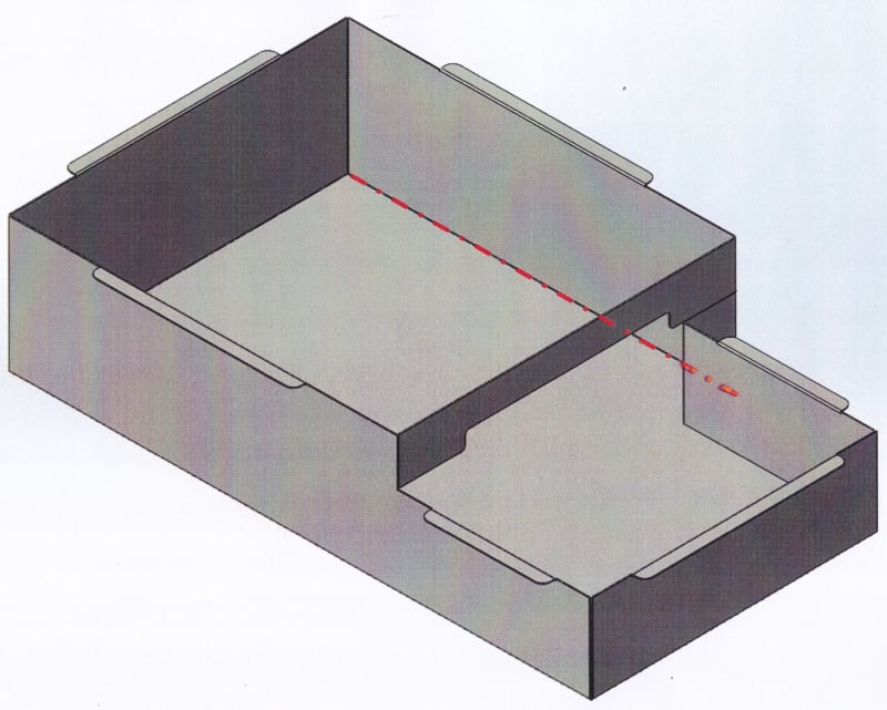
4th step - bending this line:
7_htvabj.jpg


5th step - bending this line:
8_pysj4k.jpg


6th step - bending this line:
9_m33bur.jpg


7th step - bending this line:
10_anqvbg.jpg
 
Replies continue below

Recommended for you

Here is a press brake normally used for making parts like this:
Here is another style (note the shape of the tooling):
Some of the steps will require bending near the end of the tooling so that the workpiece past the end of the tool doesn't get bent. That is not a problem, but step 5 will be a problem in a normal brake press with a normal bending tool, because the upturned features produced in steps 2 and 3 will hit the side of the platen/slide. Step 6 has to be done in a tool that's the exact length of the bend, and in step 7, the piece sticking up will hit the side of the platen.

It may be possible in non-standard tooling or in some other style of machine that I'm not thinking of at the moment. What happens to the path of the free ends of the previously-bent areas is what you need to take into account here.
 
It could (almost) be made. At least one.
It is not manufacturable.

There is one location where you have a blind cut with no kerf. That's not possible.

You seem to have modeled all the bends as perfect 90° angles. In reality there must be some radius.

You have modeled every bend perfectly. Perfectly on the desired bend line. Perfectly orthogonal. perfectly 90°. No real manufacturing process will be capable of doing all of those things perfectly every time.

The "bridge" is especially susceptible to not mating correctly because its position relative to what it needs to connect to is subject to variations of 5 (if I counted correctly) processes.

If we guess that you do want to weld all the seams, then although you have done a reasonable job of reducing the total length of welding, the welds you have left are all of the difficult ones.

There is potentially a lot of wasted stock relative to commonly available sheet sizes.

I don't know how perfectly flat an square you imagine the finished box to be. But there is still a lot of welding and there will be distortion.
 
How many are you making, hundreds or hundreds of thousands?
Is corrosion resistance an issue?
It is poor material utilization (what is the overall blank size vs finished material) and the welds will be very difficult (inside sharp corners).
If you are not making many I would look at making the walls separate from the bottom. You could make the corners very rounded and have just a couple of welds. Then you could put a bottom on it. More weld but simpler.
If you are making a lot of them then deep draw the entire part, just add the bridge afterwards.

= = = = = = = = = = = = = = = = = = = =
P.E. Metallurgy, consulting work welcomed
 
Thank you for replying, it's very important to me.
Some important remarks following your questions:
[ul]
[li]We are considering manufacturing only several parts like this, so a wasted stock and manufacturing time and cost aren't so critical.[/li]
[li]There are radii in the bendings (1 mm radius) that aren't seen so good in the original pictures.[/li]
[li]The tank must be corrosion resistant.[/li]
[li]We initially thought of other options of bendings, and it's still an option - but I really want you to keep comment on this design, because I really want to learn about this (sheet metal bending) technology and its capabilities.[/li]
[li]If someone has a link to a good guide (with tooling examples) of sheet metal bending - it will be great.[/li]
[/ul]

BrianPetersen
1. Do you have more examples of tooling that isn't the standard one?
For example, I found a nice and interesting illustration of a special tool:
4_k2ozmb.jpg


2. Regarding your comment about the problem in step 5 - isn't there an option to work with the machine in the picture below in which the length of the bending tool is about the bending length of the 5th bending line, and hence the bends from the 2+3 stages will protrude out of the machine?
2_rnpfgc.jpg


3.Is there a solution (even not a standard one) to the problem of stage 7? I am very curious.

MintJulep
1. Regarding your remark "There is one location where you have a blind cut with no kerf. That's not possible." - can you explain it please? I am not sure I understand what blind cut and kerf mean?
2. Why are the left welds are the difficult ones?

EdStainless
1.Why will the welds (inside sharp corners) be very difficult? Is there any case in which there will not be inside sharp corners welding?

Thanks you all !
 
Blind_cut_u9im7o.png


Difficult welds = Where 3 surfaces come together. Direction changes.

If you quantity is only "several" I think you will find that tooling costs will not be acceptable to you.

Also, looking closer, you won't be able to make this bend. At least not in the sequence you propose.
cant_bend_f23qeo.png


It's great that you are thinking about things like this, and are curious about the whys.

You really need to make a visit to your sheet metal shop with the model of your desired finished part and have a long conversation with someone there.
 
The special-tool fabrication department could make that bend happen, but any time you need to call upon the resources of the special-tool fabrication department, your cost shoots up.

The hand-tool hammer + clamp + workbench department could make that bend happen, too, but any time you need to use a hammer, the edge of the bench, some C-clamps, and some judiciously-applied fixtures to make that bend happen, your accuracy and repeatability are out the window.
 
No, but they might have a water-jet cutter that might come close enough.

Ain't gonna be easy, ain't gonna be cheap, ain't gonna be perfect.

I'd take a good hard critical look at the actual system requirements and first ask why the part has to be shaped that way, and then ask why it has to be built that way instead of building it in two simpler parts ... like two completely separate simple boxes that aren't even attached to each other ... or even better, one bigger plain simple box.
 
Not a zero-width cut as much as shearing?

Still, as soon as welding is in the mix it's not clear that there is much savings in getting highly complex bends that are more difficult than the welds that are replaced.
 
I believe, just because something can be done - it's not necessary that it should be done.
I'm with of few of the others, It probably can be done but is it worth it for just a few pieces - look at simplifying the method, accept a less complicated folding sequence with a couple of extra welding steps.

It is a capital mistake to theorise before one has data. Insensibly one begins to twist facts to suit theories, instead of theories to suit facts. (Sherlock Holmes - A Scandal in Bohemia.
 
Hey everyone and thanks for your tips and comments.
Now, after reviewing what is wrong with this design for learning purpose, I would like to move forward to the next stage - improvements suggestions.
For your convenience I am attaching XT format file to those who want to express their idea through CAD model.

I thought to split the design to 3 different sheet metal parts as described below:
*Each color represents a different part that will be welded to its neighbour parts.
2.01_v5lzve.jpg


What are you saying?
Any other good ideas?

Thanks to this great group.
 
The piece that gets bent in steps 2, 3, and 7. IE; The edge of the box on the north east of the images. Can that be made as a second piece?

Piece 1; Fold 3 edges of the box on a standard press.

Piece 2; Fold 4th edge of box on a standard press with your elbow and bridge thing. If need be - add tabs so when mating to the main box you have an easy mechanism to attach.

Weld/rivet/glue/seal together. Pending operating environment.
 
Status
Not open for further replies.
Back
Top