Continue to Site

Eng-Tips is the largest engineering community on the Internet

Intelligent Work Forums for Engineering Professionals

  • Congratulations GregLocock on being selected by the Eng-Tips community for having the most helpful posts in the forums last week. Way to Go!

Sheet metal racing intake design 4

Status
Not open for further replies.

sierra4000

Automotive
Oct 17, 2013
224
Hello Alls,
Can you help me with design of the intake for my V6 racing engine?
Currently I have a intake manifold that I think does not able to use the maximum potential of my engine.
In the Annex is a picture of my engine with current intake and chart from engine dyno.

Is it possible to achieve improve just by changing the length and diameter of pipe while retaining the original design? I mean split plenum with two throttle body,
or is this totally inappropriate design?

Thank You for your ideas !


Replies continue below

Recommended for you

What red line are you comfortable with? At first sight the intakes could be a bit shorter, it looks as though they might be responsible fro the torque peak at 3000 rpm, moving that up would help.

Cheers

Greg Locock


New here? Try reading these, they might help FAQ731-376
 
splitting an engine into two separate "engines" will return greater output when dual turbochargers are present, many years ago one of our test engines was a ford 302 cubic inch 5.0 (4.9L) engine with dual t3 turbo's (two of the stock turbo's from the 4 cylinder svo mustangs were used)

the engine made close to 250 hp on our engine dyno naturally aspirated, with both turbo's shared into the factory plenum it made 370 hp
when the intake plenum was split into two separate and divided banks using two different throttle bodies, the engine made just over 400 hp at the same boost level, the intake plenum was the only change

these tests were done back to back in the time it took to bolt on the plenum (about 15 minutes)
 
Thank You GregLocock!
safe maximum is 7000 rpm, because of using the stock connecting rods.
I prefer a broad power curve


yes,
I now have a very long runners
total length of 16 "- manifold tube is straight ID 1.85 "

 
Thank You decipha !

This very interesting experience!!
 
Here is camshaft specifications:
131962_492071537490839_1918389236_o.jpg
 
What would be the new(correct) tube size for this RPM range 4000- 7000 rpm (I prefer wide power curve)

I have hydraulic camshafts 230/238 at 0.050 " advertised duration 265/273 valve lift 0.475" LSA 115
intake open 4 BTDC and close 46 ABDC
exhaust open 50 BBDC and close 0 ATDC

in fact Xtreme Energy lobe for V8 Ford mustang modular engine

Corresponding the pipe ID 1.85" for engine 3.98" bore and 3.35" stroke?
Or is too large and lose any flow speed?
What plenum volume ?

heads specifications: 1.86/1.56 valves, flow 236 CFM intake/176 CFM exhaust.
compression ratio: 10:1

Thank You for Your time and experience!

Radek

sorry my english(google translator [glasses] )
 
Twin plenums can work on a V6 (assuming it is even firing -ie firing every 120 degrees). They generally work on the principle of resonance charge tuning.

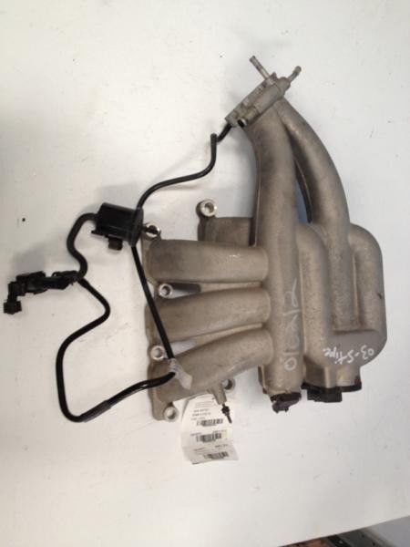
Here is a picture of an intake manifold I was involved in the design and development of


It is twin plenum with two connectivity tubes that change it into a single plenum. Variable resonance tuning is quite often confused with variable runner length tuning when they're not the same thing at all. You will get some pressure wave tuning from the length of your runners tuning at the correct rpm range. The resonance runing comes from matching the volume of the plenum itself and matching it to the engine cylinder size, runner volume and valve timing. This is a complicated process. I used a 1 D cycle simulation code back to back with extensive dyno testing to do this. Twin plenums when sized appropriately will tune well at lower end (say 2000-3000) and then again at high end 5000 rpm plus- but will tend be non optimal in the mid range in the region where most engines have peak torque (thats the reason why the intake manifold pictures from the Jaguar V6 becomes a single plenum again)

Once the tuned lengths are sorted out for intake manifold design I would then focus on detail design- such as eliptical bell mouths for the runner entrys, minimising the bend losses of the intake runners (yours have a nasty bend on them but there are ways to minimise the impact of this bend loss).
When ascertaining plenum volumes for resonance tuning there is a trade off of resonance tuning boost and smaller volume to benefit throttle response


Sideways To Victory!
 
Thanks Marquis!

This means that V6 may be single plenum is better for mid range?
This means that my torque dip at 4000 may be caused by  twin plenum effect?
How I can minimise the impact runner bend loss?


But how do I determine the runner size and the shape,?
some Pipemax experience?

Radek
 
Radek it IS possible that the torque dip at 4000 rpm is due to this. The way to be surer is to not look at torque but at volumetric efficiency (you can calculate it from the fuel flow and air flow ratio). A dip in torque can be due to ignition or a due to excessive knock limit etc or due to airflow/tuning aspects. To get better engineering insight you separate and look at volumetric efficiency: its what separates the hot-rod-ding Dremel wielding, Smokey yunick worshipping opinionated peasants from the engineers!

To minimize bend loss effect on a runner you can squash the runner shape around the bend such that the upper radius r1 and lower radius r2 difference are minimized, effectively going from a circular cross section to a racetrack shape. This is to minimize flow separation at the short side as much as is possible. You can also have a wider base area at the short side to decrease velocity there.

To calculate your effective tuned lengths you need to know your target peak power and peak torque speed.
I have a first cut calculation package before launching into GT Power/Ricardo Wave use


Sideways To Victory!
 
Oh,
Therefore all those V6 intakes that shape [surprise]
I mistakenly think - that runners racetrack shape is used by because of 4 valve oval port


so if fuel map shows a decrease at 4000 and lambda is ok - means that a bad efficiency at these RPM?
I think that's my case. Even in the dyno video is evident acoustic suction change at these RPM.


My target peak power about 6500-6800 (wider is better) and peak torque speed about around 5000 RPM
 
Is your exhaust 3 pipes into a collector?
Similar to this?

If so, how long are the primary pipes?

Basic 4 into 1 headers on motorcycles were famous for creating torque dips somewhere below max HP when exhaust wave action got out of synch and shook up scavenge flow activity upstream into the intake. When carbureted they were twice as bad due to multiple carburetion enrichening sometimes even visible, as stand off.

I wonder if the inferred decreased air flow at 4000 could be from exhaust reactions. Do you have another system you could easily try before chopping up the intake? At least maybe a longer collector?
 
Primary 1.75" x 36" total lenght with 3-1 merge collector to 2.5"x 34" pipe

892080_556752094356116_1683662342_o.jpg
 
Status
Not open for further replies.

Part and Inventory Search

Sponsor