Continue to Site

Eng-Tips is the largest engineering community on the Internet

Intelligent Work Forums for Engineering Professionals

  • Congratulations Toost on being selected by the Eng-Tips community for having the most helpful posts in the forums last week. Way to Go!

Shell Mesh Contact

Status
Not open for further replies.

Doodler3D

Mechanical
Jan 20, 2020
188
Hi,

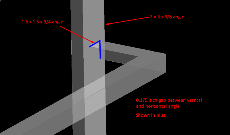
What would be a good way to mesh a joint between two structural components from a mid surface shell model? (ANSYS WB 2014)

1. A gap with rigid elements or
2. No gap and connected components

Thank you!

Screenshot_82_kbep2j.png
 
Replies continue below

Recommended for you

terminate the horizontal member on the mid-plane of the vertical flange.

depending on your s/ware if you mesh both (horizontal and vertical members) at the same time the mesher will understand and do things right.

alternatively …
1) mesh the horizontal member.
2) you should be able to, depending on the s/ware you're using, copy this mesh (these nodes) to the vertical member planes (mid-surfaces).
3) you should then be able to mesh the vertical member and embed these nodes.

the brutal olde school way would be to mesh things then see where the horizontal member nodes line up with the vertical nodes, and join them together by hand … moving nodes, splitting elements (creating new nodes) … like I said, brutal !

another day in paradise, or is paradise one day closer ?
 
Thank you rb1957


So using MPC or rigid elements to connect two mid surfaces of structural components could be considered as wrong? Additionally, do i define contact surface areas?
 
using MPCs = wrong … no, MPCs is an option (just not the first one I'd go to).

how to specify contact area ? … depends on s/ware. YT is a good source of "how to" videos.
oops see "ANSYS WB" … don't know, don't use … try YT.

another day in paradise, or is paradise one day closer ?
 
Status
Not open for further replies.

Part and Inventory Search

Sponsor