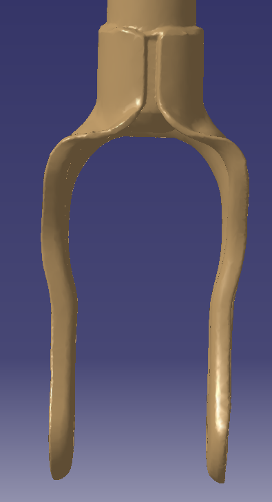
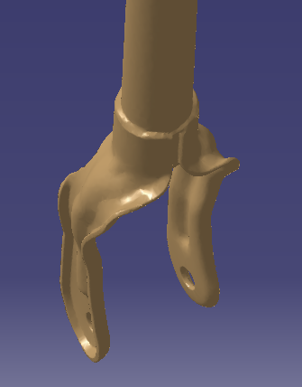
Eng-Tips is the largest engineering community on the Internet

Intelligent Work Forums for Engineering Professionals

SHOCK FORK design model 3

Status
Not open for further replies.
Replies continue below

Recommended for you

This looks rather morphed. Is it a scanned model ?

To me it seems one would use freeform modelling combined with sheet metal.
I'll give it a try.

Older budweiser
NX8.5 & NX9.0 64bit, hp z820
 
RUGmechanic,
Thanks for reply.
Yes, it is a scanned model.
I have no idea about conversion of scan data to a CAD model so far.........

CAD 2015
 
Could somebody show me how to design a part like the one shown in the two attached pictures?
Would the use of the Sheet Metal be possible in this case?

Thanks,

CAD 2015
 
Mr. Baker,

Thanks again for taking the time to reply to my thread.
The area you started with wouldn't create any problem for designing.
The real problem is the area below the welding zone (please see the attached picture).
How would you design this critical area? Can you start a model ( the dimension do not matter) similar to the pictures?

CAD 2015
 
 http://files.engineering.com/getfile.aspx?folder=2edec858-c12c-4762-accc-df85198789b3&file=Snapshot_2015-11-02_193534.png
BRACKET_-_FRONT_VIEW_qwkkow.png

BRACKET_-_TRUE_VIEW_etsfj1.png


CAD 2015
 
Why are saying that you "...have to learn how to create this part..."? It sounds like this is some sort of a 'assignment', like perhaps as part of an academic program. Is that the case?

John R. Baker, P.E.
Product 'Evangelist'
Product Engineering Software
Siemens PLM Software Inc.
Digital Factory
Cypress, CA
Siemens PLM:
UG/NX Museum:

To an Engineer, the glass is twice as big as it needs to be.
 
No.

The shape of the part is very challenging.
I have never designed something like that so far!
That's the object of my curiosity.
My current job assignments are totally different.


CAD 2015
 
Here's another part file addressing the other end of the model. It's a bit messy (I could have done a slightly better job using NX 10.0) but it gives you the shape that you're looking for.

John R. Baker, P.E.
Product 'Evangelist'
Product Engineering Software
Siemens PLM Software Inc.
Digital Factory
Cypress, CA
Siemens PLM:
UG/NX Museum:

To an Engineer, the glass is twice as big as it needs to be.
 
 http://files.engineering.com/getfile.aspx?folder=d03f9805-9343-4807-940d-5d4c939edf99&file=Fork_example-JRB-3.prt
JB,
Can you help me understand the swept feature? I'm looking at your example in 10.0.2.6. Swept(17) use the 2 sections and Bridge Curve(15) as the only guide, but Bridge Curve(14) has a direct influence on the shape of Swept(17). Can you explain what's going on or am I just missing something?
Thanks,
John
 
Bridge Curve (14) is guide 1 and Bridge Curve (15) is guide 2; each guide string is made of one curve. The "Select Curve (1)" prompt is showing how many curves make up the selected guide, not how many guides have been specified for the swept. You may need to expand the "List" panes to see the whole story.

If you edit the swept and highlight "Section1", you will see that it is made of 6 curve objects; "Section2" is made of two curve objects.
 
Status
Not open for further replies.
Back
Top