Eng-Tips is the largest engineering community on the Internet

Intelligent Work Forums for Engineering Professionals

Shoring a column 2

Status
Not open for further replies.

JStructsteel

Structural
Aug 22, 2002
1,331
0
36
US
Got a situation where a column needs to be shored to replace a footing. Plan was some channels each side of flange, all welded up as needed. What else do I need to look out for? Obviously check the channels for bending, bearing, etc. Any issues with column? Stiffeners needed?
 
Replies continue below

Recommended for you

Even if you know the (expected) loads, be a lot more conservative with the temporary design than you would be for a new structure.

Post a dimensioned sketch, preferably drawn to scale.

 
I'm with SRE. What you do depends on the loads and consequences of failure. I'm much more cavalier with replacing garage columns than I am those supporting an occupied high-rise; but both can be and are replaced under load.

If you could explain the plan view plus loading that would help. Also, are we talking a concrete column or a steel column?
 
Depends on the loads and reactions at the column. Any uplift or part of a moment or braced frame with large shear / horizontal reactions? I would be concerned with stability if column is part of LFRS.

Would you just support your channels/shoring on cribbing down to earth or an existing slab? I could see a challenge with providing enough clearance during excavation and construction of the new foundation. Do you need enough room for a whole new spread footing and pier? A photo or sketch would help. I've designed shoring to temporarily support and replace sections of damaged steel columns but not their footings.
 
Here is my idea. 20K DL, 10K LL No uplift, not part of a frame or anything. new footing interior, so just below slab. More than likely 12" thick. About a 500 sq trib to the column, bar joists, wood floors. Floor and roof above supported. Figure its not going to snow so min roof live load.

(2)-C12x20.7 channels on the flanges. Column is a W8x24.

Will crib w/ 6x6's each end. One end on a slab, other on excavated soil. Figure about 3'-6" square crib.

Will have them tie the channels together at the ends, weld to a bearing plate too.

Screenshot_2024-04-10_225002_rblphy.png
 
Need to check the C flanges for crippling, the C webs for shear buckling.
Maybe a series of vertical stiffeners for the C’s.
And need more lateral support to keep the C’s from overall lateral buckling.

 
It seems light to me. But I have not run the numbers.
FYI in bridge construction our jacking designs are the max of factored D+L or unfactored 2*D. whichever is greater. Loads in construction can be hard to predict.

I have lifted a bridge and it was almost 1.6 times what the estimated dead load was (in theory)

when in doubt...make it stout.
 
@ JStructsteel (Structural)(OP),

The sizes seems OK. I have a point, you need to transfer the load to the set up with using jack at one side , or wedges to control the deflection of the syst.
The following excerpt from FOUNDATIONS OF STRUCTURES ( BY DUNHAM , 1950,President TRUMAN era. )

UNDERPINNIGN_OF_CLMN_httfdj.jpg


He is like a man building a house, who dug deep and laid the foundation on the rock. And when the flood arose, the stream beat vehemently against that house, and could not shake it, for it was founded on the rock..

Luke 6:48
 
JStructsteel - The beams will deflect, the cribbing will compress when loaded... top of the new footing will have to be somewhat lower than the existing. Will this lowering of the column cause temporary or permanent problems with floor and roof above?

This project is in the "grey-area" that is a blend of structural and geotechnical. Geotechnical has been ignored.

1) Ten feet long beams are too short for a (theoretical) 10'0" center-to-center span.
First, there needs to be a construction tolerance on the c-to-c span, say, +3".​
Second, beams whose length is equal to the c-to-c span put unnecessary eccentric point loading on the cribbing. From the drawing, a beam length of about 12' would be a better choice.​

2) Size and depth (below ground) of the existing & new footing are not given. The cribbing will put significant distributed surcharge load on the soil. This loading may be too close to the excavation, resulting in unexpected soil settlement under the cribbing, or worse.


Once shored, the contractor is going to pour new footing up to the existing column. It will be poured down to existing soil. My thought is that the soil is already consolidated below the footing.

Not sure about the eccentricity, I am showing them at the center of the cribbing. Layout of cribbing location given by contractor, one side is going to be at same elevation as bottom of footing, other end on slab.

New top of footing will be 4-6" below grade. Footing thickness 1'-4"
 
JStructsteel said:
1) Once shored, the contractor is going to pour new footing up to the existing column. It will be poured down to existing soil.

2) My thought is that the soil is already consolidated below the footing.

3) Not sure about the eccentricity, I am showing them at the center of the cribbing.

4) Layout of cribbing location given by contractor, one side is going to be at same elevation as bottom of footing, other end on slab. New top of footing will be 4-6" below grade. Footing thickness 1'-4"

1) The beams will have deflected and the cribbing compressed...top of the new (full depth) footing will be lower than the existing.

2) Agreed... now... how about after disturbance caused by removing the existing footing?

3) I am sure... but it's your project.

4) Redraw the sketch to scale, both vertically and horizontally, and post it here. Be sure to show the size of the existing footing located in an (oversized) excavated hole that is 5' 10" deep.

 
The new top of footing can be at bottom of baseplate, or a bit lower, then they could grout.

I guess I am not sure about the eccentricity part. Are you saying they will load the edge of the cribbing?
 
JStructsteel - Grouting can and should be done, but unless the column is jacked (raised) to do the grouting, the column will be lower than it is now. The amount lower will probably be small, say, << 1 in, and this may be acceptable. However, you (engineer) make that decision, it is not something to just ignore or "pretend" is not a potential problem (say, roof ponding).

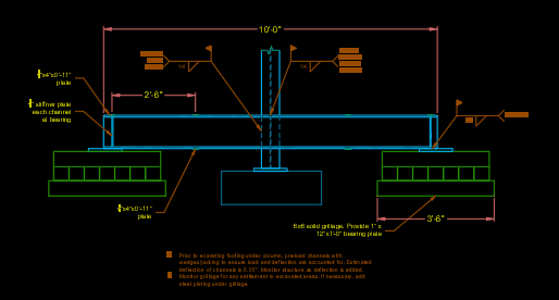
Eccentric loading, yes... more or less, the assumed point load from the beam will be off-center. Again, this could be minor... but it is easily avoided by using longer beams. Don't take any risks that are unnecessary. Also, eccentricity may NOT be minor if the cribbing is not level... a real possibility.

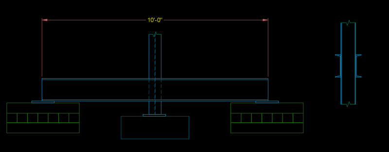
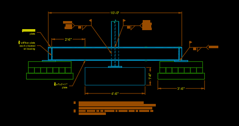
Redraw, to scale (horizontal & vertical), one thing for sure, the first two sketches are clearly inaccurate. We need to see exactly what you are dealing with... a picture is worth a thousand words.

 
Show the existing ground line and top of concrete slab on this drawing.

What about the "top of the footing will be 4' 6" below grade" plus 1'4" thick?
That must be the new footing?
Draw a separate scale drawing showing the new footing. There may be significant (geotechnical) "challenges" to overcome in that case.

 
Status
Not open for further replies.
Back
Top