Continue to Site

Eng-Tips is the largest engineering community on the Internet

Intelligent Work Forums for Engineering Professionals

  • Congratulations GregLocock on being selected by the Eng-Tips community for having the most helpful posts in the forums last week. Way to Go!

Shoring Pier Embedment? 1

Status
Not open for further replies.

MJC6125

Structural
Apr 9, 2017
120
I'm trying to figure out how embedment is determined when designing shoring piers. I have tried reading through a few different resources, but I'm still pretty confused. Here are my parameters:

ka = coefficient of active earth pressure = 0.347
kp = coefficient of passive earth pressure = 2.045
H = height of excavation = 10 ft.
I'm assuming 12" deep piers spaced at 12" o.c., just to simplify things for this calcualtion.

Here is a list of the methods I've looked into:

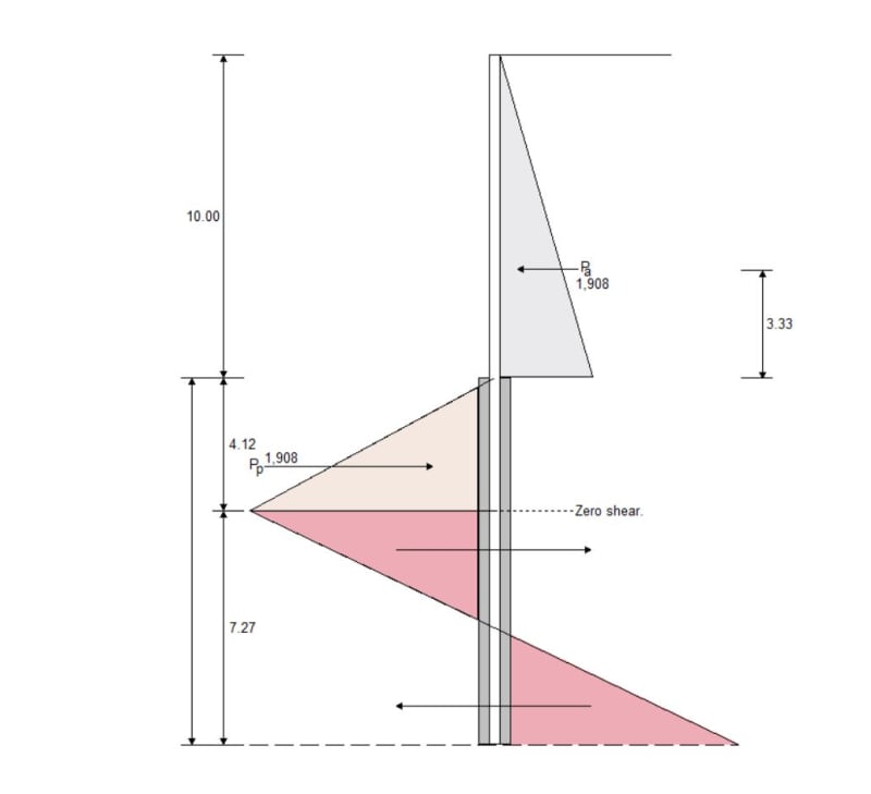
1. I have RetainPro, and I used their Soldier Pile Retaining Wall module. The image below is the pressure distribution that they use.
retain_pro_b2mize.jpg


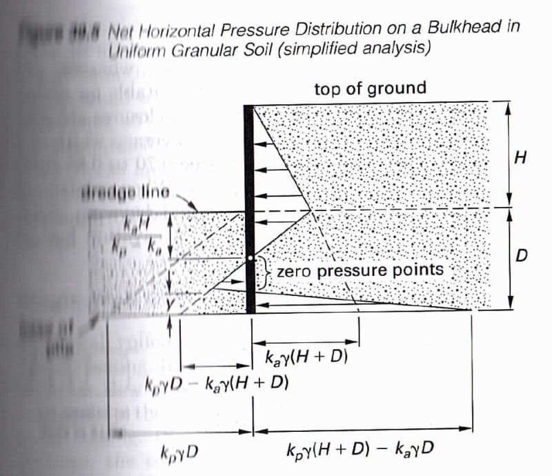
2. I have been studying for the PE and the image below is the pressure distribution they show in the Civil Engineering Reference Manual.
CERM_oi7yjw.jpg


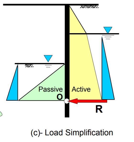
3. I read through the California DOT trenching and shoring module and they show the following pressure distribution:
CDOT_zahj0u.jpg


As far as I can tell, these are all saying something different for what embedment to use, but I could be wrong. Which of these are correct? I'll probably have some follow up questions once I know what a good starting point is for determining embedment on shoring piers.
 
Replies continue below

Recommended for you

There are multiple methods to find the embedment depth. The two I know of are Free Earth and Fixed Earth. Then there are multiple ways to handle the factor of safety. Some add a factor to the embedment(1.2 to 1.5) or some factor the passive resistance (Kp).

Take a look through the US Steel Manual ( It should explain things pretty well.

I'm not sure what's going on with the output from RetainPro. Ka doesn't drop to zero like it's showing. Its more like your 2nd example which is showing net pressures and 3 which is showing total pressures.
 
Find a copy of Foundation Design by Wayne C. Teng. He discusses his Conventional and Simplified Methods for designing cantilevered sheet pile walls. The Simplified Method is much easier, not iterative, and works fine. Just don't mix up the steps for his two methods. Do what Teng says for the Simplified Method; don't add steps from his Conventional Method to his Simplified Method. Your third diagram is the Simplified Method.

 
Better run a soil-structure interaction program. Active and passive pressures are two extreme cases which may not apply for embedded retaining walls.
 
OK, I think I'm finally starting to understand after reading through the Sheet Pile manual (for granular soils at least). Thank you for that. Pretty sure the CERM diagram is incorrect in where it shows the dimension "y". It shows this going to the point of zero pressure, but the sheet pile manual shows the same dimension going to the point where the slope of the passive pressure on the low side of the wall reverses. As far as I can tell the Sheet pile manual is correct.

When you are designing shoring piers (i.e. 12" diameter drilled concrete piers spaced around 2' - 3' o.c.), do you consider the portion of the pier below the lower grade to be engaging the entire soil structure or are you only checking the net pressures against the face of the drilled pier? If we were only considering the portion on the face of the drilled pier, I think this would through a wrench in using the conventional method described in the sheet pile manual.

What is a soil-structure interaction program? What types of programs or calculations, would you recommend I use when designing shoring piers?
 
I'm not sure if I'm understanding your question in the second paragraph. The portion of the pier below the bottom of excavation engages a wedge of soil. Depending on soil type and pier spacing, the two adjacent piers could act on the same wedge of soil (look up shadowing). If you're asking if the retained soil between the piers applies an active pressure, then yes, it does. Soil arching can affect the force.

I use SupportIT for designing soldier pile and lagging walls and sheetpile walls. For drilled pier walls I'll use LPile, design the pile with stickup, and use a distributed load (resolved for the tributary area if piles are spaced) along the pile stickup. I've reviewed other engineer's work that used CT Shoring. The estimated deflection on CT Shoring always seemed a little underestimated (typically half as much as SupportIT). We saw deflections on the job larger than they estimated using CT Shoring. Keep in mind that typically deflection will control your design. A 25' piece of steel will bend a lot before it buckles.

My advice, go work underneath someone that really understands this topic, ask them a million questions, do a couple of designs by hand and using a software package to compare and to make sure you fully understand what's going on. Never trust a software package unless you've done a side-by-side calc by hand. It can take you a long time but once you trust the software, the better you'll feel about your designs.
 
What you are calling shoring piers seems to be what most other people call soldier beams or soldier piles which are discreet, vertical or near vertical, non-gravity retaining wall elements that can be cantilevered, braced, or tiedback. Normally, soldier beams are drilled or driven in place at about 7' to 10' on center and lagging boards or some other type of temporary and/or permanent facing spans horizontally between soldier beams and retains the soil behind the wall. Therefore, the earth and surcharge pressures above the bottom of the exposed wall get multiplied by the soldier beam spacing while the lateral pressures behind and below the bottom of the wall get multiplied by the beam flange width or concreted drill hole diameter for permanent walls. For temporary sheeting walls, it is common to ignore the lateral pressures acting on the back of the soldier beam or drill hole below subgrade. For passive resistance supporting soldier beams, it is common to multiply the beam flange width or concreted drill hole diameter by a factor of 2 to 3, depending on competency of the passive soils or on the particular design code that has to be followed. Check out any edition of AASHTO's bridge design manual for more information on permanent soldier beam wall design.
I never heard of anyone using soil structure interaction to design sheeting walls. Sounds like overkill unless there are unusual circumstances like very soft or loose soils and the wall will be close to adjacent structures. CT Shoring by CivilTech calculates a structural beam deflection without consideration of soil movement. I do not find CivilTech's deflections to be significantly inaccurate. Modeling a wall in LPile or CivilTech's AllPile will consider the soil movement when calculating wall deflections. However, how accurate can these programs be if the user is pulling soil values out of the air with out real, local experience or testing results? GIGO?
I use CivilTech's Shoring program because the design results match what I calculate by hand.

 
I believe the OP is referring to a drilled shaft wall with spaces between the piers, without anything holding the soil between the piers (See photos on [link ftp://ftp.dot.state.tx.us/pub/txdot-info/brg/0810_webinar/galvan.pdf]Page 7[/url]). It's something that I didn't see back east but is used quite a bit out west with dry clayey soils. Spacing depends on the drilled pier diameter. I typically keep the spacing around 1 to 1.5 feet just because I'm still skeptical of the system.

I understand your point with unknowns and GIGO, but the input values used on that job were actually very conservative. All of the shoring systems (there were several) still moved quite a bit. Doing side-by-side comparisons between SupportIt and CT Shoring probably 5 years ago, everything matched up except the deflection calculations. If I remember correctly CT Shoring factors the deflection, not sure why.
 
Correct, I am talking about the closely spaced drilled shaft piers like shown in the images. I'm in Denver, and that's what they use when excavating for residential projects with basement walls close to a property line. These are typically used for temporary shoring only.

I'm a structural engineer, but we've been asked to design more and more of these shoring piers, so I'm trying to get a handle on what is all required. Working underneath someone that really understands the topic isn't exactly an option, but I figured I could get a little more insight on eng-tips.

MTNClimber, if you were to design one of these shoring systems with 12" diameter piers spaced at 3'-0" o.c., would you say that each pier is engaging a 3'-0" strip width of soil for the passive pressures? I know you mentioned you keep the spacing to something smaller, but I'm wondering hypothetically.
 
For embedded retaining walls, such as sheet pile wall, soldier pile wall, diaphragm wall, especially with multi struts or anchors, a soil-interaction program that can model staged construction and arching effects, such as Plaxis, Wallap, Sigma/W, will predict more realistic results. Active and passive pressure theory are two extremes and appropriate for gravity retaining walls; however for an embedded wall design, earth pressure much more than active pressure at active side can happen due to arching effect, how can a hand calculation consider this?
 
A good reference for embedded retaining wall design is CIRIA C580, recently superseded by C760. Another popular FDM program for embedded retaining wall design/analysis is FLAC.
 
HENRYZAU, you rhetorically asked, "how can a hand calculation consider this?" You are correct; hand calcs cannot easily or accurately handle it. However, for the overwhelming majority of non-gravity retaining walls, both temporary and permanent, the sophisticated design methods you mention are not used or needed. Occasional projects with special circumstances may required such methods. The key to success is knowing when the more sophisticated methods are needed.

MJC6125, the wall you are designing is no different than what I described. It is just more like a tangent pile or secant pile wall. However, the effective passive resistance width supporting the vertical beam or drilled pier should not be greater than the actual beam spacing. Without installing lagging between your drilled piers, spaced at 3' on center, either the concreted drill hole needs to also be at least 3' diameter or, if smaller, you would need the retained soil to be cohesive soil that will relax, erode, or fall out between drilled piers. Cohesive or not, unsupported soil between drilled piers can be problematic.

 
I'm in Denver too. There are several ways to look at it. Do not assume that the pier will be able to engage passive resistance for 3 feet of soil. You typically won't have that ability with a 12" pile along the Front Range.

The way I would look at it is using an effective width by including passive arching. Effective width (Weff) is equal to Passive Arching Factor (A) x the diameter of the shaft (w) (Weff = A x w). A = 0.08 x friction angle. A is anywhere from 1 to 3 (max). Depending on the type and stiffness of the soil will dictate A. If you're in the Denver clean sands, then you can get away a higher A value. If you're in the interbedded clayey sand/sandy clay or in claystone, then A will be smaller.

I know this is a residential job but just so you know, AASHTO recommends that passive resistance be ignored for depth below excavation level no less than 1.5 times the effective pile width. I like to take this in account since contractors are always excavating further than shown on the plans. AASHTO also recommend increasing embedment 30% for temporary shoring.

10 feet could be starting to get too high for a closely spaced 12-inch diameter drilled pier wall, depending on your surcharge loading. You may need to increase the pier diameter or reduce the spacing. Especially if you're going to design for the Denver Fire Truck loading. If your project is in Denver then you have to design for their fire truck loading unless you prove that a truck cannot get close enough to the wall.

Not for nothing, but an inexperienced engineer design a shoring wall without anyone above them to check their work is concerning. The last thing you want to do is have something go wrong while someone is in the hole. Having someone competent review your work is very important. Do not design anything strictly based on what you read on a forum. Research, read papers and design manuals, and find some solid backing to your design process.
 
Fitting username for Colorado.

I have seen shoring designs by some other soil engineer's in this area, and based on what I saw they are providing less pier embedment and reinforcing then what I would use.

One project had a 5' deep excavation, and they used 12" diameter piers spaced at 3'-0" o.c. embedded only 5'-0" into the ground.

The other project had a 10' deep excavation, and they used 12" diameter piers spaced at 3'-0" o.c. embedded 14'-0" into the ground.

Based on this discussion, I do feel like there is a lot that I don't fully understand when it comes to soils still. I think I'll steer away from doing the shoring designs for now.
 
The Colorado residential engineering designs can be scary. There's a bunch of designers here that don't understand shoring design but still pump out plans. I've seen one instance where someone just copied plans from a previous job... no real calcs to back it up. It's mind boggling that there aren't more construction related accidents in this state.

Honestly, I'm not sure how much longer I can last out here. It's tough to compete against people that don't do things to a standard and get away with it. I heard that some people want introduce legislature to do away with requiring a license to practice engineering in CO... must be the lack of oxygen up here.
 
PEinc,those programs I mentioned, which are considered sophisticated by you, are used on daily basis for routine design in my office and by many other similar consultants I know. So it appears we live in different environments. Don't know how long it takes you to do a hand cal. for the OP's problem. For an experienced geotech engineer, it should take about 1-2 hours to set up a Wallap model (for a simple, symmetrical problem) and finish it. It takes another 5 minutes to change the wall embedded length and re-run it with nice output of active/passive/porewater pressure distribution, deflection/bending/shear profiles. Design/analysis is only half the job done, what matters is how the wall behaves in the field, so monitoring or OM is essential especially in urban areas. Regardless of the methods (hand cal or numerical) used, agree that if the engineer doesn't fully understand earth pressures theory or the program limitations, doesn't have a feel of what reasonable parameters should be used or has no engineering judgement, then it's GIGO and could lead to catastrophic failures or overly conservative designs.
 
HENRYZAU, I did hundreds of design-build projects in many areas of the U.S. using hand calcs back in the 70'S and 80'S. Since then, we just design, teach contractors how to do the work properly, and keep them out of trouble. We try not to do hand calcs anymore - now usually just to show reviewers that the computer program results can be verified by hand calcs. The few of us here finish several design submissions per week. We can't afford to waste time doing hand calcs. Our design-build experience is what sets us apart from our competitors. I see many engineers that know how to use powerful software but haven't a clue if their designs are buildable, appropriate, economical, or safe. I doubt we live in different environments; we just try to use the proper tool for each application.

 
Status
Not open for further replies.

Part and Inventory Search

Sponsor