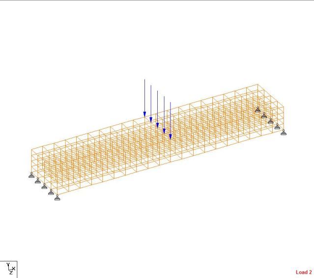
To start to re-acquaint myself with finite element analysis, I am trying to model a very basic simply supported beam using solid elements in STAAD.
In STAAD, the beam is (4) x (4) x (20) solid blocks (with concrete material assigned). I applied the 10-kip point load as (5) 2-kip joint loads at midspan.
I calculated the shear at midspan by multiplying each (midspan) solid's resulting shear force (SXY) by the solid's cross sectional area. This resulted in V = 5 kips, as expected.
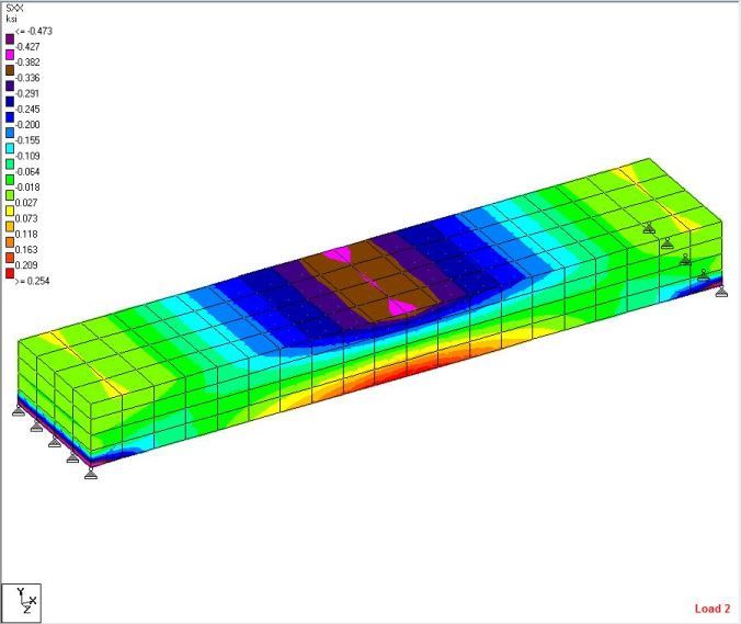
I calculated the moment at midspan by multiplying the normal force by the distance from the (mid-height) centroid by the Area (SXX * d * A). This resulted in only M = 14 k-ft.
Am I doing something incorrectly with the moment, or could I expect that much of a moment reduction when the "point" load is distributed over the width of the section? (resulting stresses attached in *.csv file)
Thanks in advance...


Span Length, L = 10 ft
Point Load at Midspan, P = 10 kip
Shear, V = P / 2 = 5 kip
Moment at Midspan, M = P * L / 4 = 25 kip-ft
Point Load at Midspan, P = 10 kip
Shear, V = P / 2 = 5 kip
Moment at Midspan, M = P * L / 4 = 25 kip-ft
In STAAD, the beam is (4) x (4) x (20) solid blocks (with concrete material assigned). I applied the 10-kip point load as (5) 2-kip joint loads at midspan.
I calculated the shear at midspan by multiplying each (midspan) solid's resulting shear force (SXY) by the solid's cross sectional area. This resulted in V = 5 kips, as expected.
I calculated the moment at midspan by multiplying the normal force by the distance from the (mid-height) centroid by the Area (SXX * d * A). This resulted in only M = 14 k-ft.
Am I doing something incorrectly with the moment, or could I expect that much of a moment reduction when the "point" load is distributed over the width of the section? (resulting stresses attached in *.csv file)
Thanks in advance...


