Continue to Site

Eng-Tips is the largest engineering community on the Internet

Intelligent Work Forums for Engineering Professionals

  • Congratulations cowski on being selected by the Eng-Tips community for having the most helpful posts in the forums last week. Way to Go!

Simply supported beam supported at base 5

Status
Not open for further replies.

dl8860

Structural
Jan 29, 2020
7
So at university we all learn that a simply supported beam with length L loaded with a point load P at mid-span will have a maximum bending moment at mid-span of PL/4 and always zero bending moment at the supports.

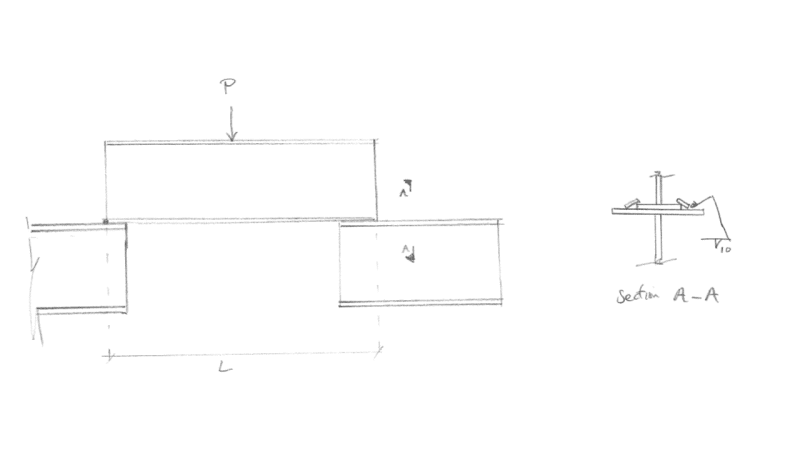
I have a case of a slightly complex piece of grillage, but one component is essentially an I beam that is supported at either end by bearing onto another I beam. The connection is simply some shear plates welded along the bottom flange of the top beam onto the top flange of the bottom beam, to restrain the overlying I beam along it's own axis.

When I model this (only the top beam) using structural software and offset the beam vertically upwards by half it's depth to have the support point at its base, I get moment resistance at the ends of the beam, yet it is simply supported.

This of course has the further effect of reducing my mid-span moment.

Is it OK to use this more beneficial bending moment profile? Is the bending only internal to the beam, and not passed on via the connection to the beam below? Note in my modelling the joint fixity at the ends of the main beam has no rotational restraint, there is only moment there because of the offset.

Thanks.
 
Replies continue below

Recommended for you

Good on you for catching the problem. Since you've identified the connection as a theoretical pin, your analysis should reflect that.

Not sure what software you're using, but most of them will us a Rigid Link to create those offsets (even if you can't see it). So you may have inadvertently fixed your beam. If this is part of a larger analysis that requires the use of 3d software, then double check the beam end releases and make sure it's free to rotate at its ends - that should fix the rigid link problem.

If you're only looking at one beam - then your PL/4 is all you really need.
 
grillage_kplazs.png


Interested in the bending in the top beam.
 
An odd connection to be sure - restrain the vertical while allowing it to move side to side? Kinda looks like a home-made crane rail clip.

Your L is really going to be the clear distance between the two lower beams. If your clips are all the way at the ends, then yes - you'll get some rotational restraint from the compression/tension couple formed between them. But it's not going to be all that much, and if your sketch is to scale the beam is stiff enough that it probably wouldn't matter all that much.

 
from a computer analysis perspective if the full system is modeled this type of condition can end up restraining the flange movements which in turn restrains the cross section rotation at the ends based on the member stiffness's resulting in some end moment, I'd likely look at the upstand beam on it's own and apply it's simple support reactions to the beams below and detail as a bearing condition.

My Personal Open Source Structural Applications:

Open Source Structural GitHub Group:
 
"An odd connection to be sure - restrain the vertical while allowing it to move side to side" … isn't this an example of a roller joint ?
Maybe designed by someone with a theoretical background, rather than a practical one ??
practically, I'd weld the RH like the LH end … simple tack weld, or bolt (at both ends) the piece into the frame.

another day in paradise, or is paradise one day closer ?
 
phamENG said:
An odd connection to be sure - restrain the vertical while allowing it to move side to side? Kinda looks like a home-made crane rail clip.
It actually won't move side to side because of another member that runs into the page as we look, that's just a simplified sketch.

Good point about L being the clear distance between, perhaps a better way to model it is one Z support where the shear plate is and another where the end of the lower grillage beam is, which will provide some rotation fixity because of the couple.

@Celt83, I haven't modelled the lower beam in my analysis.
 
rb1957 - absolutely. That's exactly what it is. Though that particular configuration seems odd to me. The OP didn't specify it's purpose though, so perhaps I should reserve my judgement of normalcy until that gets cleared up.
 
If all you're doing is modeling the one beam - then why are you using a computer model? Your best bet is assume simply supported, do your PL/4, and be done. By the time you determine the fixity from your point reaction and the "tie down" plate (which will either be iterative or a quadratic solution - determine minimum contact area for steel on steel bearing and use the centroid of that area to find the distance to the center of the weld group for your plate) and determine the reactions and stresses in the welds, etc., you might save a few pounds of steel. But, because it's framing into the lower beams along the same axis, you'll need to consider their stiffness, too, as that will impact the rotational restraint of the center beam and the resulting shape of the moment diagram. Just doesn't seem worth it unless this is going to be recreated 100 times to achieve the economy.
 
do you have one side modeled as a roller or are both ends defined as pinned not allowing any translation?

If both ends are pinned, no translation allowed, you should be seeing end moments = Horizontal Reaction X Distance from Cross Section Centroid to Bottom of member.

My Personal Open Source Structural Applications:

Open Source Structural GitHub Group:
 
I am using a computer model because it is a much more complicated piece of grillage than that sketch shows, and it isn't just a simply supported beam, as I said in my OP. This beam has other members passing through it (into the page) and supports a tubular above it.

It requires computer analysis to compute the reaction values at 6 different support points, but I am interested in just the end condition of this one beam at this point.

Of course for just one beam I would use PL/4, it's just that the notion of weather the end-condition is simply supported or not that's important.

I am using the software to give me my bending moment distribution, the issue is that in the model when I don't use an offset it gives me zero moment at the ends. When I use an offset it gains moment resistance. I want to know a) if just purely on the basis of offsetting I should keep the moment resistance and b) how this ties in with my actual restraints, as shown in the detail of the sketch.
 
People just love to jump on the 'you don't need a computer for everything' bandwagon without reading the content of the actual thread. I've done about 30 other such simple non-computer calcs for this design, and assure you I know when each is appropriate.
 
dl8860;
post a screen shot of your model with the support restraints turned on. It's likely you have translation restrained on both ends which would result in end moments when the supports are offset to the bottom of the beam.

My Personal Open Source Structural Applications:

Open Source Structural GitHub Group:
 
@Celt83 that's a good point, the upper beam is restrained along it's length, that's what the shear plates are there for. In that case would you say the end moment is realistic?
 
I think this is a case where it would be a mistake to be too confident in your FEM analysis results. Let me explain...

My engineering judgment says that this is a simply supported beam. At the very least, I would design it that way. The FEM analysis showing how restraint at the bottom flange can result in beam end moments is something to think about. But, I don't think it should invalidate your engineering judgment. There are lots of little things that come into play when you start introducing rigid link / rigid offsets into a simple model like this. I don't know that this model is 100% accurate.

My recommendation would be to design it as a simply supported beam. Then, if you believe the end moments may be real, make sure that your design is capable of resisting these forces as well. But, DON'T allow the FEM results to reduce the design you'd get treating it as a simply supported beam.
 
I agree with the hand calc … but there's something to be gained in figuring out why the s/ware isn't behaving as expected (particularly for such a simple case).

Perhaps open a thread in the FEM forum if it doesn't appear obvious when you look into it.

another day in paradise, or is paradise one day closer ?
 
dl8860 - got it now. When you said you hadn't modeled the other beams, it made it seem like you were only interested in the middle one from the sketch. Sorry about the misunderstanding.

I think Josh is spot on. But it would be helpful to know what software you're using and, perhaps, to have a snapshot of the model as Celt suggested. Easier to see what may be coming into play and causing these reactions. Though I wouldn't be surprised if it's some automatically applied notional lateral loading inducing a moment from the rigid offset's eccentricity.

 
Status
Not open for further replies.

Part and Inventory Search

Sponsor