Eng-Tips is the largest engineering community on the Internet

Intelligent Work Forums for Engineering Professionals

  • Congratulations waross on being selected by the Tek-Tips community for having the most helpful posts in the forums last week. Way to Go!

Simulating Welded Connection Between Two Welded Mid-surfaced Shells 1

Status
Not open for further replies.

MegaStructures

Structural
Sep 26, 2019
366
0
0
US
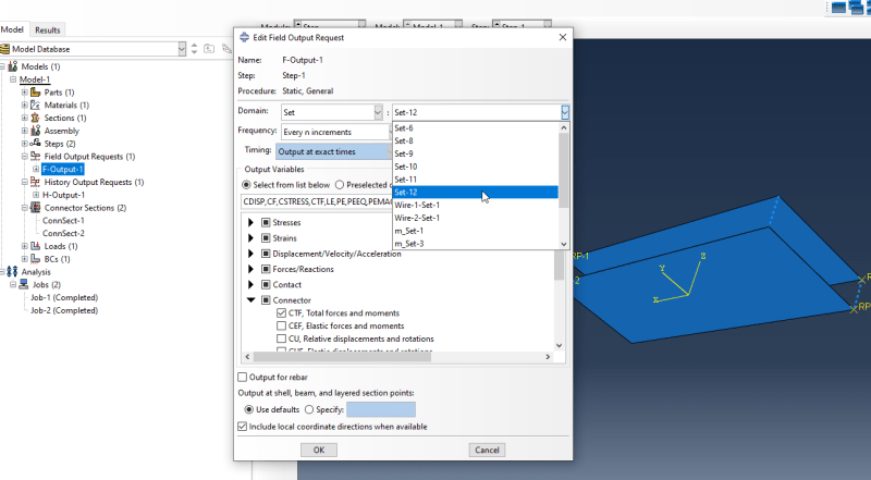
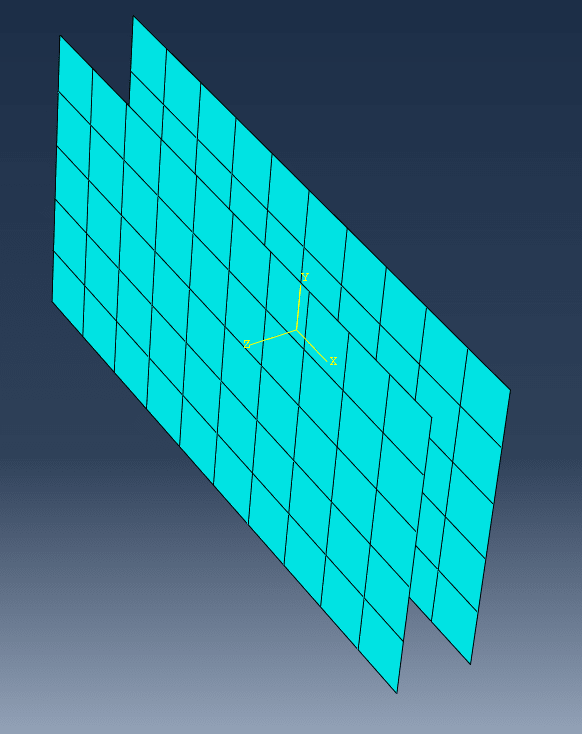
What's the best way to represent an edge weld for two shell structures modeled at midplane? I want to extract weld force to design the welds by hand.

2021-09-01_13_21_21-Abaqus_CAE_2017_Viewport__1_shyaqb.png


“The most successful people in life are the ones who ask questions. They’re always learning. They’re always growing. They’re always pushing.” Robert Kiyosaki
 
Replies continue below

Recommended for you

An MPC needs one control point to connect to multiple nodes correct? Would that work to simulate a weld?

“The most successful people in life are the ones who ask questions. They’re always learning. They’re always growing. They’re always pushing.” Robert Kiyosaki
 
No, when you apply MPC BEAM or MPC TIE, for example, you need 2 nodes and constraint is applied between them. Check the documentation chapter "General multi-point constraints".
 
Thanks FEAway. Tie constraint seems to work great, but not sure how to output the tie forces to design the welds.

“The most successful people in life are the ones who ask questions. They’re always learning. They’re always growing. They’re always pushing.” Robert Kiyosaki
 
Actually, I meant MPC TIE, not regular tie constraint. But if you want to get forces then connectors might be the best choice.
 
Great. A basic connector with U1, U2, U3 seems to work well. Is there an easy answer to "how do I see the connector forces in postprocessing?". If not I can find it in the user manual I'm sure

“The most successful people in life are the ones who ask questions. They’re always learning. They’re always growing. They’re always pushing.” Robert Kiyosaki
 
Connectors have their own output variables, including various types of forces. You can request the CTF variable to get total force in each direction for each connector.
 
Last question here, the user manual isn't very clear. To request connecter force, you must request from the "set" option. What should be included in the set? The wires that the connectors are attached to? There is no option available for the connector set.

How do you see the connector force in the results module after connector force is requested?

2021-09-01_19_20_28-Abaqus_CAE_2017_Viewport__1_c7dnp9.png


“The most successful people in life are the ones who ask questions. They’re always learning. They’re always growing. They’re always pushing.” Robert Kiyosaki
 
Yes, you should select a set to which the wires belong.

When viewing the results you have to enable this option: View --> ODB Display Options --> Entity Display --> Show connectors.
 
Status
Not open for further replies.
Back
Top