Continue to Site

Eng-Tips is the largest engineering community on the Internet

Intelligent Work Forums for Engineering Professionals

  • Congratulations IDS on being selected by the Eng-Tips community for having the most helpful posts in the forums last week. Way to Go!

Simulation of front beam in bending 1

Status
Not open for further replies.

evenjl

Materials
Oct 7, 2015
13
Hello everyone!

I am currently working on a project as an introduction to my Master thesis.
I have spent some time doing tests on different beams in the lab and I now want to simulate some of them using ABAQUS.
First off, I want to re-create a simple experiment with a simply supported beam subjected to a point load in the midspan.
The analysis itself is not that difficult to do, but my lacking experience with FEA software is causing me some minor problems.
I have attached a picture of the beam geometry.

My question is: What is the best or most effective way to replicate (draw) this geometry in ABAQUS?
My main thought was to use the extrusion-function and assign a given thickness to different partitions of the beam.


Thanks

evenjl (NORWAY)
 
 http://files.engineering.com/getfile.aspx?folder=7203d2d4-8e33-402e-869d-d9baab8231a4&file=Beam-geometry.JPG
Replies continue below

Recommended for you

Hello,
Drawing the midsurface and extruding as shell might be easiest if you need to create the geometry from scratch. This will however give you a slight inexactness if the cross section is not uniform. In the picture it looks to me like inner and outer radii do not "match". Also, shells will not describe your geometry perfectly at T-junctions.

If you have a CAD model you can extract mid surfaces. I myself, prefer solid elements and would also consider that (drawing inner and outer contour, then extruding).

Here is a good read for you: [URL unfurl="true"]http://50.16.225.63/v6.14/books/gsk/default.htm?startat=book01.html[/url]

It covers topics like element selection. It could be used spice up your report. :)

Good luck!
 
Thanks StefCon. I really appreciate the help.

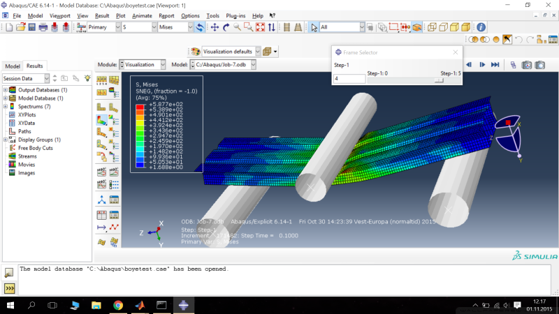
I have used the last week to read the manual and search the web for possible explanations to why my force-displacement data vary or deviate so much from the "real" data. I know there could be thousand of reasons for this, but I have tried my best to reduce these to the minimum. I have attached a picture of the curve (the blue solid line one is based on data from the lab, while the other 3 are from Abaqus).


The beam was created drawing the midsurface and extruding the cross section using shell elements. This will of course give a small inexactness describing the geometry, but will this justify the big gap between the curves alone?
The supports and the nose (which is working as a point load on the beam) are modeled as analytical rigid cylinders. The intercation is "General contact" and the normal behaviour is "hard contact". Material properties are obtained from the material test (tensile testing of a specimen). Extrapolation of the stresses are done by using the Power-law. I have runned the analysis with different mesh sizes.
I have double checked the geometry and every parameter I can think of.

Some comments or tips would really help.


Thanks
 
 http://files.engineering.com/getfile.aspx?folder=ed9c3924-80d6-460a-8204-6dd3b279f3a6&file=lab-vs-abaqus.png
Picture of the model
3-point-bending_js527g.png
 
Your image says, that your real structure is much softer.
Does the real structure show some kind of buckling or collapse?
Is that a static process? Have you verified, that the explicit analysis does not contain any significant dynamic effect?
 
The problem is probably due to the rolls bending, which you have excluded from your model by using rigid surfaces for the rolls. This can be quite significant, particularly for relatively small diameter rolls such as yours. The rolls will bend and mostly likely tend to make contact with the beam towards the outer edges rather than across the whole section as in your case. The only way to avoid this is to model the rolls as a solid 3D cylinder. The beam as thin shells is probably ok as it is.

 
Thanks guys, I appreciate the help.

Mustaine3: Yes, the real structure is softer. And yes, some buckling do occure, but not until half way through the experiment - I don't think this will justify the big gap alone.
This is a quasistatic experiment - the cylinder is moving down about 10mm per minute, or 0.1667 mm/s. I have plotted the internal and kinetic energy - no significant dynamic effects present.

corus: I tried to replace the rigid cylinders with solid cylinders. No major difference in the force-displacement curve.
 
Status
Not open for further replies.

Part and Inventory Search

Sponsor