Continue to Site

Eng-Tips is the largest engineering community on the Internet

Intelligent Work Forums for Engineering Professionals

  • Congratulations SDETERS on being selected by the Eng-Tips community for having the most helpful posts in the forums last week. Way to Go!

Simultaneous requirements 1

Status
Not open for further replies.

Rwelch9

Mechanical
Apr 22, 2020
116
SR_4_icsldl.jpg

Hi guys,

I have spoken on this forum before about this exact same job .

The is two sets of coaxial cylinders .

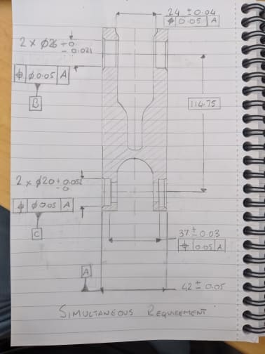
Is controlling them using simultaneous requirements as showing on my sketch correct ?

I have a design engineer who is questioning how the relationship between the two set of pockets is tolerance.

I cannot find anything on the use of simultaneous requirement exactly like this however.

I look at this as Datum A ( mid plane ) , then we will have two perpendicular axis to Datum A at a basic of 0 , 114.75 , these axis will have a tolerance zone of 0.05 .

then my 4 pockets , there axis will have to fall within this 0.05 tolerance zones ?


Any knowledge is appreciated

Thanks
 
Replies continue below

Recommended for you

RWelch9,

This looks like a legitimate application of simultaneous requirements. I don't see anything wrong with it.

The position tolerances would control the spacing and orientation the two sets of coaxial cylinders, as well as the coaxiality of each set.

Evan Janeshewski

Axymetrix Quality Engineering Inc.
 
Rwelch9,

You aren't going to find a figure or sentence in the standard that covers every possible case - most have to be extrapolated (and in some cases - extended within reason).

It might help to better understand the mechanism behind Simultaneous Requirements. Per Y14.5-2018 para 7.19:

ASME Y14.5-2018 para 7.19 said:
A simultaneous requirement applies to position and profile tolerances that are located by basic dimensions related to common datum features referenced in the same order of precedence at the same boundary conditions. In a simultaneous requirement, there is no translation or rotation between the datum reference frames of the included geometric tolerances, thus creating a single pattern.

Features held in Simultaneous Requirements have DRFs which are constrained in location/orientation relative to each other even if the DRFs themselves are not fully constrained in all 6 DOF. As the standard suggests, the effect is as if all the features were specified as part of a single pattern and this is probably the best way to think of it. This is shown in the difference between figs 7-47 and 7-48. In 7-47 even though the rotational DOF around A is not constrained, the tolerance zones for the slots are fixed in rotation relative to each other - the effect is the same as if the slots had been specified as part of a "2X" pattern. In 7-48 SEP REQT is utilized to allow the tolerance zones to rotate relative to each other about A, and they no longer behave as a pattern.

In the case of your part you have 4X tolerance zones which are fixed in basic location/orientation relative to each other (and to datum feature A), as if they were a single pattern. Assuming x is up/down, y is perpendicular to the page, and z is left/right that means that even though A only constrains (u,v,z) and the tolerance zones are free to translate (x,y) and rotate (w) - they must do so together as if they were a single pattern.
 
axym,

It was either yourself or another person on this forum who suggested this method of dimensions .

I though it was a great idea.

I just wanted to double check the call out was correct and it was the design engineer who maybe didn't quite understand the call out

Thanks
 
Chez311 + axym

On another note , if you look at my sketch you see we have the 42mm width , we also have the 37mm + 24mm width.

Although i do not give the actual depth of pockets , do i have to show this on the drawing to allow for proper tolerancing stacking ?

Thanks
 
Rwelch9,

I don't think that you have to show the depth of the pockets. The way that you've dimensioned the drawing, the bottoms of the pockets are controlled in terms of their distance apart and the location of the center plane of each set of 2 pockets. This isn't wrong, but it's probably somewhat unusual. You would have to do a stackup calculation to determine the range of possible depths of the pockets relative to the outer A surfaces - the drawing does not control this depth directly.

Evan Janeshewski

Axymetrix Quality Engineering Inc.
 
Status
Not open for further replies.

Part and Inventory Search

Sponsor