Continue to Site

Eng-Tips is the largest engineering community on the Internet

Intelligent Work Forums for Engineering Professionals

  • Congratulations IDS on being selected by the Eng-Tips community for having the most helpful posts in the forums last week. Way to Go!

Sinewave filter no load current 2

Status
Not open for further replies.

ahendawy85

Mechanical
Oct 11, 2011
6
Hello everyone. I have a question related to Sinewave filters. I am running a 800 KVA VFD with a Sinewave filter at the output side. The VFD is meant to run a submersible medium voltage 3 ph motor. My question is concerning no load. At no load the VFD reads a load of 70 A, it is my understanding that the filter acts as a load on the drive so this is why there is a current present. I want to know however if this value is normal or high. I tried asking the manufacturer but I didn't get much help. Is there any way I can calculate the filter's no load current at say 60 hz? I couldn't find it in its manual. Also does this loade represent a derating factor when I connect a load to the drive, meaning if the motor load is 100 A will I see 170 A (Motor load + filter load) at the output? Obviously I am not an electrical eng so bear with me.... thanks.
 
Replies continue below

Recommended for you

The filter which we presume is between the VFD and the motor does not see 60Hz but a complex waveform that is hundreds of times higher frequency than 60Hz. I suspect the high reading is due to your apparently running the VFD with only the filter as a load.. You cannot use a hand held to get a good current read on the drive's load due to the complexity and frequencies present. The drive's own internal circuitry is probably being confused by the incorrect load it's finding itself driving.

If the drive is the correct one for the motor and filter is the correct one for the application, hook it all up and run it. Don't experiment piece-meal "to see what happens", as doing that with VFDs leads to lots of confusion as you're finding. :)

Keith Cress
kcress -
 
The thing is the drive itself is displaying an output current of 70 A. The thing is I know by experience that when I hook up the motor it will run smoothly. I am looking for an explanation as to why it draws this high load when no motor is connected. I am sure it has something to do with the inductors and capacitors, but what?
 
You haven't given us much to go on. The least we need is motor rated voltage, capacitor values and the carrier frequency. Then, one could see if the 70 A is plausible or not. I think that it is. Capacitor's primary role is to pass high frequency current, and your capacitors obviously do that.

Don't worry about it. The motor consumes mostly inductive current, so the capacitive current in the capacitor compensate that to some extent and do actually decrease the current demand on the inverter.

If the inverter supplier is a reputable one, I would not worry about things I do not understand - at least not in advance. Just trust them. But if you want to be safe, write them a question about this and ask them to have speed, voltage, frequency and load at a few representative operating points.

Or just forget about it.

Gunnar Englund
--------------------------------------
Half full - Half empty? I don't mind. It's what in it that counts.
 
Keith and Gunnar put it more eloquently that what I was originally going to say, which was ..

"Fuggedaboudit" (American mafia style slang for "Forget about it"). In other words, you are overly concerned.

Most people who make sine wave output filters are overly proud of their "secret sauce" to publish the schamtics on the web it seems, but in a nutshell, you have a reactor in series with the load to add inductance, but what makes a sine wave filter more than a load reactor or even a "dV/dt filter", is the fact that it will add an RC circuit in PARALLEL to the motor to absorb the higher level harmonics as heat BEFORE it goes down to the motor (gross over simplification, but you get the idea). So that part of the circuit has some power resistors in series with capacitors that are connected in a delta, and then there are bleeder resistors in parallel with the capacitors. With no load, that part of the circuit has losses in it, because it is NOT interacting with the inductive load of the motor, it is just sitting there making heat via the capacitor charging and discharging to the bleeder resistors, and all of THAT current is going through the power resistors first as well, so there are losses there.

In reality, you should not have the output of the drive running without the motor connected, it is just wasting energy and stressing components needlessly. So you are concerned over what reaction you are seeing during a task you are not supposed to be doing in the first place. I think your concern is as to whether or not this is something you will see when running the motor, but don't be. Apples and oranges.


"You measure the size of the accomplishment by the obstacles you had to overcome to reach your goals" -- Booker T. Washington
 
Generaly, VFDs or Variable frequency drives has an in built load.

In VFDs the power from the source is converted into high voltage DC, through switching rectifiers.

The efficiency of the No Load or standby power consumption is in the efficiency of this process.

Once you have the spec of the motor to use, you can vary the output frequency or voltage (Through switching) to control the speed / torque of the motor.

Please go through the label on the VFD, download its manual online and see what is the rated standby power or current.

If it is 20% more than the rated standby current, there might be shorting withing the controls of the VFD. Which is dangerous.

Hope that helps
 
I disagree.
The only appreciable "load" presented by a VFD that is not running a motor is just whatever it takes to run the PC boards and cooling fans. On a VFD that big, the fan load might be substantial, but not 70A! Besides, if the load is showing on the DRIVE display, that would NOT be inclusive of any parasitic loads for the drive itself, the display would only be showing the load going OUT from the inverter section.


"You measure the size of the accomplishment by the obstacles you had to overcome to reach your goals" -- Booker T. Washington
 
itsmoked answered your question you just did not understand the answer, this is an excerpt from a Fluke 87 5 meter it reads drive output where others do not.

( Correctly measure pulse-width modulated motor drive signals

Until now, there hasn't been a multimeter able to accurately measure adjustable speed drives. But the Fluke 87V is designed specifically to handle these complex signals. Think of the potential productivity you'll gain by taking the guesswork out of drive system troubleshooting. Measurements are correct each and every time.

Unique function for accurate measurements of noisy pulse-width modulated AC voltage. Measures correctly at the ASD and at the motor terminals
Accurately measure the frequency (motor speed). Frequency measurement not affected by the ASDs carrier frequency
Measure AC current with an optional current clamp accessory
Compare reading from the 87V with the display on the ASD
Special shielding blocks high frequency, high-energy noise generated by large drive systems)

Check out the Fluke web site for further explanation, there is a lot of good info on that site.

Chuck
 
If Fluke, at last, has done something that works with PWM signals, I am the first to congratulate.

They haven't been able to do so before. They haven't even understood the problem.

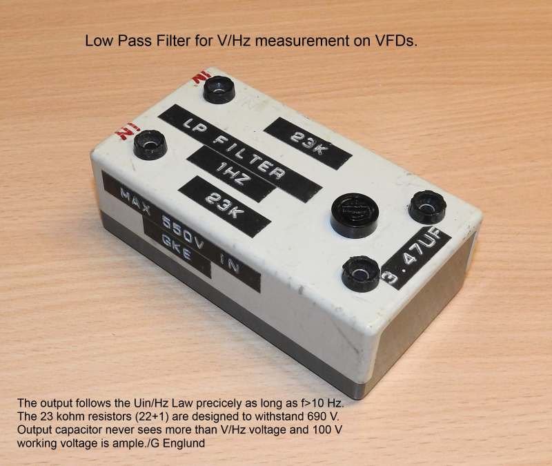
For correct measurements, I use a symmetrical 1 Hz low pass filter. I then get the V/Hz ratio directly on the DMM and, if needed, I multiply with Hz to get actual RMS voltage.

Gunnar Englund
--------------------------------------
Half full - Half empty? I don't mind. It's what in it that counts.
 
The previous posters covered the reason why the current is flowing.

I'll add that you probably shouldn't do what you did. The output filter is expecting a motor load. When loaded, the VARs produced by the capacitors are consumed by the motor. The series inductor in the filter carries a high PF current and drops the voltage at the inverter output a tiny bit. Without the motor, the capacitors present a highly leading load. In this case the series inductor boosts the heck out if the inverter output voltage. The damping and bleeder resistors will limit the resonant voltage rise from blowing it up right away, but it is still stressing the heck out of the filter.
 
Hi Gunnar

Will a simple RC circuit suffice or does your filter configuration require an op amp version with a few more bells and whistles?

Chuck
 
Yes - the simpler the better. Passive. See attached picture.

This filter was designed for 500 V but has been "upgraded" to handle 690 V. It is important to understand that flash-over voltage for small resistors can be as low as 250 V peak. So you need to se several in series to handle the 1000 V peak that exists in a 690 V system.

The capacitor never sees more than the V/Hz voltage. Usually no more than around 10 V. I have used the filter shown for more than thirty years without any mishaps.

1_Hz_low_pass_filter_lzbzgi.jpg


Thanks, Doug, for the excellent upload picture feature!

Gunnar Englund
--------------------------------------
Half full - Half empty? I don't mind. It's what in it that counts.
 
Status
Not open for further replies.

Part and Inventory Search

Sponsor