Continue to Site

Eng-Tips is the largest engineering community on the Internet

Intelligent Work Forums for Engineering Professionals

  • Congratulations SDETERS on being selected by the Eng-Tips community for having the most helpful posts in the forums last week. Way to Go!

Single Angle X-braced Frames 2

Status
Not open for further replies.

MacGruber22

Structural
Jan 30, 2014
802
I have reviewed related posts but am still unsatisfied. [URL unfurl="true"]https://www.eng-tips.com/viewthread.cfm?qid=399108[/url]

So...what effective length are people using for single angle X-braced frames in R=3 SDC A/B buildings? They are braced at their intersection with a single bolt in an OVS hole. I am not a fan of using these single angles but apparently that is the standard for self-storage buildings. And, the prototype building I am trying to base my design on appears to have used the recommendations from this report ( which recommends an unbraced length of 1/2 the total length and K = 0.85. These recommendations don't seem to mesh with anything else I can find and seem to fly in the face of AISC Table 4-12, eccentrically located single angles, as well as AISC chapter E.5.

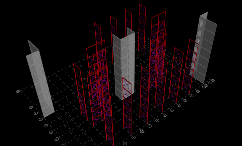
I would love to just make these tension-only, but my drift and load distributions depend on sticking with the X configuration.

-Mac
 
Replies continue below

Recommended for you

I can't imagine with standard storage building proportions that the compressive capacity of teh angles will be all that much even if you used half the length.

I don't understand how your load distribution would be drastically affected by them being tension only. I can understand the building drift argument, however I'd just look at increasing the thickness or leg size. They may have given you an example building, but there's no way everything is the exact same. Either the location (and therefore the loading) or the size of the building will be different enough that you can just hang you hat on that hook when they ask why the sizing is different.
 
Jayrod - this is a 7-story storage building 90x170. Pretty unique around these parts.

Jayrod said:
I don't understand how your load distribution would be drastically affected by them being tension only.
I don't know what to tell you, except that it does, and particularly so when the braces are working in combination with masonry shafts. I do not want anymore lateral load going into my masonry at this point. I have done enough high-rise tension-only strap bearing wall systems to know how quickly the stiffness distribution of the system is affected by minor adjustments in brace areas, etc.

I understand the example building is not going to be the same, but I am not trying to re-invent the wheel too much. Our client *is* the builder and they are very particular about keeping things similar, or at least the design logic similar to previous jobs. They also want optimization of steel weights. I am working with the hand that has been dealt to me, in many respects. There isn't enough time in the day to explain the quirks of this client, but they pay our bills and keep coming back.

I am leaning towards just using the eccentric angle tables in the manual with an unbraced length of 1/2 the total length...in lieu of trying to manipulate KL in RAM since RAM assumes concentrically loaded braces. This approach feels reasonable as it accounts for the tension member bracing but also reduces the angle capacity based on the eccentric gusset connection.

-Mac
 
For a 7 storey building, I would likely not be using single angle X-bracing.

Rather than think climate change and the corona virus as science, think of it as the wrath of God. Feel any better?

-Dik
 
If you use the recommendations of 1/2 the length and K of 0.85, an L6x4x3/4 in a 10x10 frame would have an LRFD tension capacity of 225 kips and a compression capacity of 155 kips (KL = √(10² + 10²)*1/2*0.85 = 6 ft), so it is something if the angles are large and the frames are small.

I would not be using those recommendations, though. The Engineering Journal article Stability Design of Cross-Bracing Systems for Frames (which came out 27 years after the paper you referenced) evaluates the actual stiffness of the tension brace instead of just assuming it is able to brace the compression brace.

I don't see how any of these recommendations conflict with Table 4-12, but I would be sure to still include the adjustment to your effective length found in Section E5 since you are only attaching one of the legs of the angle to the gusset plate.

Structural Engineering Software: Structural Engineering Videos:
 
dik said:
For a 7 storey building, I would likely not be using single angle X-bracing.

I don't disagree. I used HSS on the last 5-story self-storage I did (different client without all the constraints). It is way more efficient on top of being more predicable. Again, I am stuck where I am.

Programming PE said:
so it is something if the angles are large and the frames are small.

Yeah, not what I have. I have 21 total frames. Average of 30 kip LRFD demand on braces at level 1. I agree with your statement about the lack of a conflict - I misspoke. I meant to refer to the vast difference between the older testing on single angles recommending the reduced length versus E5 equations for effective KL/r. I will read that more modern journal - I missed that one.

model_iqnxpa.png


-Mac
 
I don't normally use HSS for bracing... connections can be pricey... when I do, I usually use a slotted gusset plate and no end caps

Rather than think climate change and the corona virus as science, think of it as the wrath of God. Feel any better?

-Dik
 
ASCE 10 is also very handy for determining the effective length of single angles, the equations from E5 are essentially one subset of the equations presented in ASCE 10.
 
MacGruber - have you tried applying the column brace force and stiffness equations to this situation? In other words, is one the flexural stiffness of your angles high enough to qualify as nodal bracing per appendix 6 of AISC 360? If the answer is no, then unbraced length is L. If the answer is yes, then what happens when you apply the brace force to the angle while it is receiving its max tension? If it checks out, then you're good - unbraced length is L/2. If it fails, then unbraced length is L.
 
phamENG, I don't believe it is that simple. The eccentricity needs to be accounted for in single angles which is what the effective length equations in E5 (as well as ASCE 10) are accounting for. Alternatively, one could design for the combined axial and flexure via chapter H (but who wants to do that?). Therefore, the effective length will always be greater than the unbraced length, whether L or L/2.

ASCE 10 allows the crossing point of x-bracing to be considered as an effective brace point for the compression member if the tension member sees at least 20% of the force as the compression member.
 
Flotsam said:
ASCE 10 allows the crossing point of x-bracing to be considered as an effective brace point for the compression member if the tension member sees at least 20% of the force as the compression member.
I will sure to check out ASCE 10. I didn't interpret pham's comment as suggesting to ignore the connection eccentricity, but I don't think that direct column bracing method would work for this condition since a lot of the bracing stiffness will come from the tension force in the brace rather than only its section properties. It has been awhile since I looked in appendix 6, but I dont recall it being able to account for tension stiffening in a potential bracing member.

dik said:
I don't normally use HSS for bracing... connections can be pricey... when I do, I usually use a slotted gusset plate and no end caps
What is your preference for slotting the tubes over end caps? For smaller axial loads, I would think end caps would be more economical.

Flotsam said:
Alternatively, one could design for the combined axial and flexure via chapter H (but who wants to do that?).
I certainly would rather not. For DD plans, I am running with an arbitrary KL of 1.0 times the full length of the angles with phiPn being from AISC Table 4-12, eccentrically located single angle. Conservative for now and I may or may not refine later.

-Mac
 
End caps Slotted connections (wrong one, screwed up), and I've had a fabricator confirm this, are less costly I understand. And for smaller loads, HSS is not normally used.

Just thought of it... can you crush the tube and use normal bolts? I've flattened HSS web members for trusses, but never thought of it for x-bracing.

Rather than think climate change and the corona virus as science, think of it as the wrath of God. Feel any better?

-Dik
 
dik said:
End caps, and I've had a fabricator confirm this, are less costly I understand. And for smaller loads, HSS is not normally used. And for smaller loads, HSS is not normally used.

Thanks, dik. I would just say that if braces are at exterior walls where they need to support components and cladding wind from metal stud infill, HSS is really the only way to go even when brace force is low.


-Mac
 
I fixed this... original posting was backwards...

Rather than think climate change and the corona virus as science, think of it as the wrath of God. Feel any better?

-Dik
 
Flotsam - not suggesting you ignore it, but as I interpreted the OP the main question was regarding the unbraced length to use in finding the buckling strength. So that's what I was focusing on.

MacGruber - essentially you're wanting to rely on catenary action in the tension angle. I'm not convinced that would provide any meaningful addition to the brace stiffness or force it can resist over the flexural resistance.
 
10-4 phamENG, I see you were only talking about defining the unbraced length.

While I can't find any specific reference to the derivation of ASCE 10's 20% rule, much of the document is based on testing. I have used these equations many times for single angle members, but in non-building structures. However, considering AISC references ASCE 10 in the comm. of E5 I would say it is not inappropriate to use other information presented in the document.
 
That Lui paper from AISC Eng Journal 2013 is very scholarly, but the 14 step process is generally unfriendly.
ASCE and TIA have allowed L_effective = L/2 for buckling for single-bolt at crossing angles for decades.
Like most of what structural engineers do, this simplification might not perfectly align with the differential equations, but it is pretty darn close, and agrees well with testing for a broad range of angle sizes and geometries. And agrees with intuition.
 
Status
Not open for further replies.

Part and Inventory Search

Sponsor