Eng-Tips is the largest engineering community on the Internet

Intelligent Work Forums for Engineering Professionals

  • Congratulations waross on being selected by the Tek-Tips community for having the most helpful posts in the forums last week. Way to Go!

Single phase plate fan running backwards 2

Status
Not open for further replies.

RobWard

Industrial
Nov 7, 2001
269
0
0
GB
Hi,
I wonder if someone can help me out?
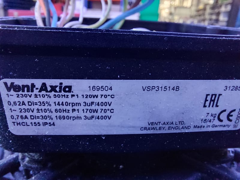
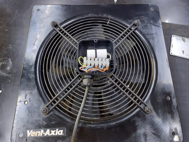
We've repurposed a single phase plate fan and it seems to be running backwards.
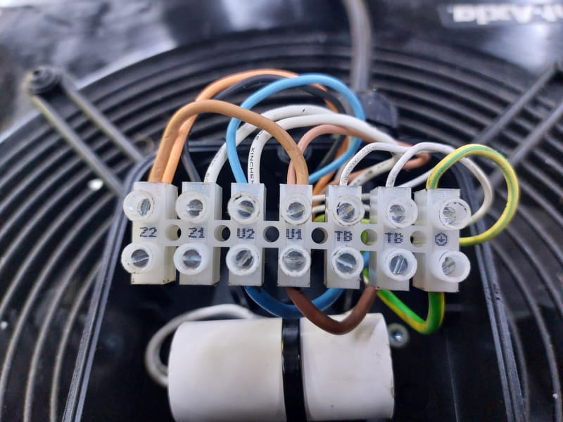
Could someone advise on how to change the wiring to swap rotation?
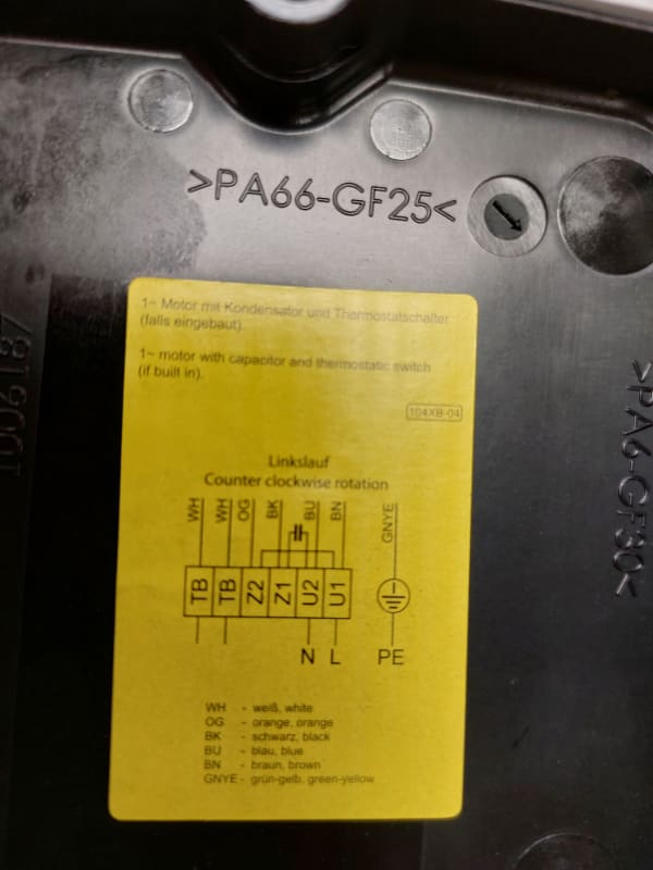
It is wired as per the diagram attached,and I don't think it's ever been altered but it's definitely running backwards - the airfoils are running "feathered edge" first and as you look at the fan it's running clockwise, contrary to the wording on the diagram.
(It's been an awkward install so just turning the fan around and running it backwards would be difficult (and would annoy me everytime I looked at it, to be honest).
I've searched the forums but it would be handy if someone with more knowledge than me could offer any assistance with this particular motor.

Many thanks!

Rob

"I love deadlines. I love the whooshing noise they make as they go past." Douglas Adams
 
 https://files.engineering.com/getfile.aspx?folder=4b75d826-a540-4201-9091-5a12e7bf2fec&file=20230105_121028.jpg
Replies continue below

Recommended for you

More details on the motor would be good (manufacturer / model no, power etc.

Also here's the picture for anyone else

20230105_121028_xgib79.jpg


Remember - More details = better answers
Also: If you get a response it's polite to respond to it.
 
Thanks for taking a look.
There's not a great deal of information but hopefully this will help:
20230105_142047_z43eev.jpg
fan_2_m15cwo.jpg


"I love deadlines. I love the whooshing noise they make as they go past." Douglas Adams
 
Can't recall where to find the generic IEC diagrams - but the NEMA version that is applicable is at:
NEMA MG 1:2011 Section 2.48 Schematic Diagrams for Capacitor Start Motors, Reversible (2.48.1.1 for no thermal protection, 2.48.1.2 for thermal protection) Figures 2-22 thru 2-25(b).

See link.

Converting energy to motion for more than half a century
 
 https://files.engineering.com/getfile.aspx?folder=2ad8ace5-99eb-4298-a0e1-6ee07dd03a0e&file=NEMA_MG1_Sect2-48.png
Thank you Gr8blu.
Trying to work out just what I'm looking at - is it fig. 2-24, and I should be transposing the orange and blue leads?
(I'm out of my comfort zone here - as a lowly sparky, 3 phase motors I can just about understand, but single phase motors are like witchcraft!)

Rob

"I love deadlines. I love the whooshing noise they make as they go past." Douglas Adams
 
The wiring diagram and actual seem to be different.

From L to r the diagram goes white white orange black blue brown
The actual wiring seems to go white white orange blue black brown.

So maybe swap the blue and black wires and stand back....

Remember - More details = better answers
Also: If you get a response it's polite to respond to it.
 
Chances are that you can just pull the blade assembly off of the shaft and flip it. There might be a little keeper ring on the shaft, which might require a C-clip removal tool, something like that.


" We are all here on earth to help others; what on earth the others are here for I don't know." -- W. H. Auden
 
Reversing the blade on the motor shaft will not reverse the flow direction, just as reversing a right-handed screw will not turn it into a left-handed one.
 
Dear Mr. RobWard (Industrial)(OP)
I would like to submit the following for your consideration:
1. Principle, to reverse the rotation; you may either (reverse the current) through the [(run winding) or the (start winding)]
i.e. (a) transposing the orange and black leads = reversing the start winding.
Or (b) transposing the brown and blue leads = reversing the run winding.
2. Do NOT "...just pull the blade assembly off of the shaft and flip it ..."
Che Kuan Yau (Singapore)
 
Many thanks for the replies.
Firstly, apologies to all - I should have made clear that the terminal block is labelled and that the wiring is correct to the labelling, it's just that the terminal blocks are in a different order to the diagram.
So, just for future reference, whilst a 3 phase induction motor would have its windings wired Un- Wn, on single phase motors is it usual to label the start windings "Z"?
I'll reverse the start winding, as suggested by Che Kuan Yau, and see what happens.
It's a good job I didn't swap the orange and blue leads as I'd suggested!

20230106_071041_hzylx3.jpg


Thank you all so much for taking the time to help.

Rob


"I love deadlines. I love the whooshing noise they make as they go past." Douglas Adams
 
Well I can report that we have a success!
Thank you all for your help - you have saved me an awful lot of work and I'm gladdened to see the fan running correctly now.

Rob

"I love deadlines. I love the whooshing noise they make as they go past." Douglas Adams
 
Great. Thanks for coming back to tell us. So many just vanish...

Remember - More details = better answers
Also: If you get a response it's polite to respond to it.
 
...like the magic smoke from an incorrectly wired motor...

"I love deadlines. I love the whooshing noise they make as they go past." Douglas Adams
 
Status
Not open for further replies.
Back
Top