MelBWasHere
Structural
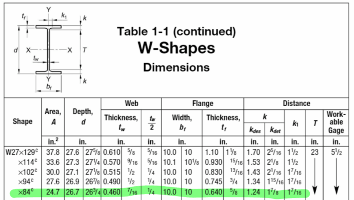
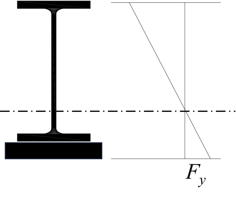
I have an (E) 50ksi wide flange beam that will be reinforced with a 50ksi 1"x12" cover plate stitch welded to the bottom flange. The beam is in positive bending (top flange in compression, bottom reinforced flange in tension).
I want to check the web slenderness. According to attached AISC 360-16 Table B4.1b Case 16, I need to calculate the plastic bending moment (Mp) and the moment at yielding of the extreme fiber (My). "Of the extreme fiber" is ambiguous to me, but it suggests that there is technically an Myt & Myc, in this case moment at yielding of the extreme tension fiber (bottom flange/cover plate) and moment at yielding of the extreme compression fiber (top flange).
I naturally thought to use Myt since that's where the coverplate is, but figured it would be more conservative to use Myc since that is the lesser of the two (also valid when considering My = FySx, where Sx = the minimum elastic section modulus taken about the x-axis, per the index).
However, while calculating, I realized Myt > Mp, which confused me since the plastic moment should be larger than the yield moment. This inequality suggests that permanent deformation occurs before yielding, which doesn't make sense to me. I understand why the elastic section modulus at the bottom is larger than that at the top. Can anyone explain what Myt > Mp physically means?
I thought at first it had to do with the plastic section modulus, but it remains the same, regardless of whether we're looking at the compression flange or the reinforced tension flange. I also thought maybe Mp = FuZx, but AISC defines it as FyZx.
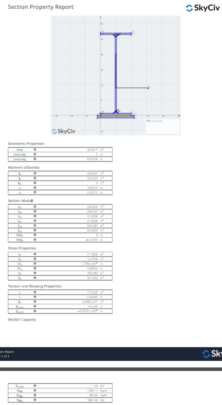
Values:
Myc = 50ksi*Sxc = 1028.621 kip-ft
Myt = 50ksi*Sxt = 1867.696 kip-ft
Mp = 50ksi*Zx = 1389.11 kip-ft
Sxc = 246.869 in3
Sxt = 448.247 in3
Zx = 333.387 in3
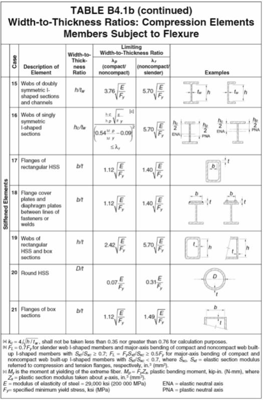
I want to check the web slenderness. According to attached AISC 360-16 Table B4.1b Case 16, I need to calculate the plastic bending moment (Mp) and the moment at yielding of the extreme fiber (My). "Of the extreme fiber" is ambiguous to me, but it suggests that there is technically an Myt & Myc, in this case moment at yielding of the extreme tension fiber (bottom flange/cover plate) and moment at yielding of the extreme compression fiber (top flange).
I naturally thought to use Myt since that's where the coverplate is, but figured it would be more conservative to use Myc since that is the lesser of the two (also valid when considering My = FySx, where Sx = the minimum elastic section modulus taken about the x-axis, per the index).
However, while calculating, I realized Myt > Mp, which confused me since the plastic moment should be larger than the yield moment. This inequality suggests that permanent deformation occurs before yielding, which doesn't make sense to me. I understand why the elastic section modulus at the bottom is larger than that at the top. Can anyone explain what Myt > Mp physically means?
I thought at first it had to do with the plastic section modulus, but it remains the same, regardless of whether we're looking at the compression flange or the reinforced tension flange. I also thought maybe Mp = FuZx, but AISC defines it as FyZx.
Values:
Myc = 50ksi*Sxc = 1028.621 kip-ft
Myt = 50ksi*Sxt = 1867.696 kip-ft
Mp = 50ksi*Zx = 1389.11 kip-ft
Sxc = 246.869 in3
Sxt = 448.247 in3
Zx = 333.387 in3