Continue to Site

Eng-Tips is the largest engineering community on the Internet

Intelligent Work Forums for Engineering Professionals

  • Congratulations KootK on being selected by the Eng-Tips community for having the most helpful posts in the forums last week. Way to Go!

Sizing conductor rail of cranes 3

Status
Not open for further replies.

martinrelayer

Electrical
Oct 26, 2007
68
Hi all,

new 2 overhead cranes of 500 meters travel on the same busbar rail needs 900A feeding. the plan is to feed from 3 different points due to voltage drop. Voltage is 400V.

we requested single feeding but they state it's technically impossible.

what do you think on this? it is like that?

Thanks in advance

Martin.
 
Replies continue below

Recommended for you

Voltage drop is a function of how much conductor cross section area is carrying the current. Feeding from 3 points - assuming this is a single circuit is just adding parallel feeders to points closer to the load.
Option 2 is to increase the size of your power busbar, probably more expensive as you would need 500m of the large busbar while the run of parallel feeder is not going to be more than 2/3 runway length.

If the system is designed with the largest sized busbar feeder, then the single feed solution could be technically infeasible as a larger bar is not available.

Fred
 
Consider using two physically parallel but electrically independent sets of busbars, one for each crane.
... on separate runway girders, if necessary.

Mike Halloran
Corinth, NY, USA
 
Yeah I was googling but couldn't get any information on busbar systems to somehow check if there is a money issue only or if it's is technical
process wants to have both cranes reach all the lenght
 
Don't fight the problem.
900 Amps for 500 meters is already a lot of money for bus bars.
To use one point of feed may require the bars to be up-rated to 2000 Amps or 3000 Amps.
Feeder cable is a lot cheaper than bus bars.
Bus bars may not be available in large enough ratings for single point feeding.
Economics has been mentioned.
This is not always straight forward.
What are the contract details?
What does the supplier pay and what does the customer pay?
Example:
We were moving some lumber kilns.
Each kiln had a 200 Amp feed to a control panel.
There was a 600 Amp main distribution panel.
The control room ran across the end of the kilns.
I planned the main panel at one end, closest to the direction of the incoming feed.
One control panel was beside the main panel, one was about 50 feet away, and the third was about 100 feet away.
Then our owner instructed me to put the main panel in the center.
"That way we don't have to buy as much cable."
I pointed out that he was saving 200 Amp cable at the expense of 600 Amp cable.
"Yes, but we pay for the 200 Amp cable and the customer must run the 600 Amp cable to where-ever we tell him to."
Economics, right?
Almost.
He was so proud of his wit in offloading cost onto his customer that he didn't hear me tell him;
"But I went to the warehouse and measured the cable removed from the original location.
If we do it my way, we have the cable in the warehouse and won't have to buy any 200 Amp cable.
Your way, the existing cables can't be fully utilized and we will have to buy some 200 amp cable."
My voice could not reach to the top of the mountain of hubris and we did it his way and spent the extra money.
Economics?


Bill
--------------------
"Why not the best?"
Jimmy Carter
 
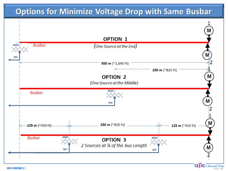
See if the suggested options on the sketch below can help to address the voltage drop issue in a long radial busbar. It is suggested to analyze the optimal solution considering evaluating technical and economical these and any other alternatives.

>>>
Voltage_Drop_with_same_busbar_uigyeo.jpg
 
Dear Mr. martinrelayer

Q. .... new 2 overhead cranes of 500 meters travel on the same busbar rail needs 900A feeding. the plan is to feed from 3 different points due to voltage drop. Voltage is 400V.
A. Based on voltage is 400V, I assumed that the project is in IEC land. I am of the opinion, consider:
a) change the motor 400V delta winding connection to 690V star. With the higher voltage, the current would be reduced by a factor of 1.73 . NB. the transformer secondary shall be 690V .
b) This would cost "nothing" as:
i) all IEC LV motors are with six terminals terminated at the cable box. It is by connecting the links straight horizontally across U2,V2,W2 terminals.
ii) all IEC LV equipment and switching devices are generally suitable for up to 1000Vac or 1500Vdc.
c) It is " best" to have only ONE source supplied at the middle. Any two or three source option would compromise on safety operation.
Che Kuan Yau (Singapore)
 
1) Can you elaborate more regarding compromising the safe operation with parallel sources?
2) It is possible to switch in and out the source based on the crane position?

I also wonder if the crane manufacturer can supply a voltage regulator within the unit in such a way that voltage drop can be compensated regardless of the position of overhead crane
 
I visualized one breaker or disconnect and multiple feeders, sized for voltage drop.
No safety concerns.
The system could be designed with a single feeder to the rail and then feeders running parallel to the rails to reduce the voltage drop.

Bill
--------------------
"Why not the best?"
Jimmy Carter
 
Dear Mr. Q. cuky2000
Q. "(Che12345: Any two or three source option would compromise on safety operation.)
Can you elaborate more regarding compromising the safe operation with parallel sources? "
A1. I am of the opinion that only [one source] gives the " best " [isolation] safety. This will give a " positive " (live/dead) status; as there is (usually?) no other (live/dead) indication along the 500m busbar.
A2. When there are two or three sources, when one source trips, the busbar is still live! The safety practice is when one source trips, it must be communicated to the other sources to trip out immediately!. This inter-trip shall be of hard-wire inter-lock when the other breakers are at different /separate locations. BTW: This is practised in the MRT railway system where the power rail is felt from different/separate sources, along the long distance.
Attention: When there are two/three sources, it is understood that any (one of the single sources) is [inadequate for the proper operation].
Appendix
a) consider increase the source voltage by say 15%, as all motors are designed to operate 10% over-voltage continuously. This would take care even when the total loading is extremely low at times. This will reduce the operation current; which would result to a lower voltage-drop,
b) introduce a under-voltage sensing relay. When the busbar voltage drops to < 90% due to the first crane operation, the second crane shall be blocked [temperately] from [starting any large motor] (usually the hoist motor?), which causes severe voltage-drop. The blockage is " temperately ". It reset automatically when the voltage had recovered.
c) install pf correction capacitor on all " large " motors to reduce the running current and therefore the voltage-drop.
Che Kuan Yau (Singapore)
 
Hi Che12345,

Thanks for letting us know your opinion regarding the safe operation of the crane bus with multiple sources.

So far I am under the impression that we are in agreement that option 2 with a single source feeding the crane bus in the middle could reduce the voltage drop approximately 50% as option 1. If that meets the voltage drop criteria for this job this will be a promising option to consider. I also like the idea of blocking temporarily the second crane during starting the first one.

Regarding multiple sources, the benefit can reduce the maximum voltage drop even further. For example, the voltage drop of Option 3 could reduce to voltage drop in 25% of the option 1.

To address the potential safety concern there are alternatives to consider. Perhaps the simplest one as proposed by Waross with a single feeder protected by a single protective device to trip simultaneously all sources.

Any thoughts regarding the merit of adding a voltage regulator with a booth transformer or other means near the crane motor?
 
The old street car and trolley bus wires ran for miles.
The trolley wires were not that heavy a gauge.
The DC stations may be miles apart.
There were typically short cross arms on the poles on one side of the street.
Carried on the cross arms were very heavy copper cables that were tied to the trolley wires at intervals.
As for the cranes:
Most solutions will work well almost all of the time.
The time when you most need dependability and stability is the time when an issue is most likely to arise.
The time that issues may arrive is when both cranes are working together on a maximum capacity lift.
You can't have a staggered start when the cranes are working together, and on a critical lift you don't want the voltage stepping up.
I would consider sizing a feeder to provide an acceptably low voltage drop at the far end of travel.
Then tie it across to the bus rails at suitable intervals.

Bill
--------------------
"Why not the best?"
Jimmy Carter
 
Dear Messrs cuky2000 , waross

Q1. "...The system could be designed with a [single feeder]* to the rail] and then [feeders]** running parallel to the rails to reduce the voltage drop]..."
A1. I may had miss-understood the configuration. I took at it that the [single feeder]* is protected by a Breaker A , feeding to a busbar B . Assuming three [feeders]** tapped the supply from the busbar B. Each [feeder]** shall be protected by an individual [feeder]** breaker X,Y,Z; which is sized to protect the feeder cable x,y,z. Load-break switches would NOT be acceptable, as they would NOT protect the feeder cable.
It shall be designed such that should the [single feeder]* breaker trips, it shall also trip out all the [feeder]** breakers. This is fine and good.
A2. However, consider what will happen when one or two of the [feeders]** breakers tripped. Unless any of the [feeders]** breakers trip is inter-locked to also trip off the feeder]* breaker, the single feeder cable which is remaining feeding the total (2 cranes) load would be heavily over-loaded/damaged! This is unacceptable.
A3. " Isolation problem" would arise. The only way to [isolate] the complete system is by switching off the feeder]* breaker or (all the three) [feeders]** breakers. The system will be "live ! " , if the feeder]* breaker and any one of the three [feeder]** breakers remain closed.
Che Kuan Yau (Singapore)
 
Mr. Che;
Think of it as one feeder composed of multiple, parallel conductors. That is common for long distances and/or high currents.

Bill
--------------------
"Why not the best?"
Jimmy Carter
 
Dear Mr. waross

Q. " Think of it as one feeder composed of multiple, parallel conductors. That is common for long distances and/or high currents ".
A. With due respect, I have different opinion. When multiple parallel conductors are used for long distances and/or high currents; the pre-conditions are [they shall be of the same routing, contact resistance, material, size, lay formation and the length]. The main [criterion is to have the same impedance], such that the [current is approximately equal between parallel conductors].
As for this case, even with the same material (Cu/Al) and size (mmsq); it is NOT possible to ensure the same routing, contact resistance, lay formation and length. It is NOT possible to ensure equal current between parallel conductors. Therefore, it is technically/practically " unacceptable? ".
Che Kuan Yau (Singapore)
 
Speak for yourself Mr. Che.
I have run multiple parallel feeders for higher currents many times and was always able to fulfill all of the requirements that you mention.
From actual field experience I see no problem whatsoever with multiple parallel conductors.

Bill
--------------------
"Why not the best?"
Jimmy Carter
 
I do concur with Waross. It is also our experience that multiple feeders and multiple sources are not an issue even for HV applications.

The use of parallel sources is a common practice in electric utilities and industrial applications.
 
Crane loads have a duty cycle that under either NEC or IEC rules can be considered. Yes I know the rules are different.

Criteria is that no part of the system can be loaded above the current allowed for the conductor.
Both cranes together draw 900 A. Most difficult loading condition is both cranes at end of runway beyond the feed point, maximum capacity lift.

A single circuit breaker (or fuse set) will protect both the crane busbar and all of the parallel feeders.
Now size the parallel feeder so that the voltage drop in the parallel circuit of the busbar and the feeder meet the voltage drop criteria.
Verify that the feeder has current carrying capacity for 900A (using the appropriate code rules)so that in the event that the crane busbar has a defective connection, the feeder is still protected from overload. In the event of a bad busbar splice, voltage drop criteria will be violated, but nothing will be overloaded from the standpoint of ampacity.
The feeder can be connected to the busbar at points similar to option 3 (but no transformers), connecting at more locations and even running the entire runway length, and connecting every 50m would also be OK, Just do the calculations for the selected arrangement.

While some code rules limit voltage drop what the equipment really cares about is that the voltage is between the upper and lower tolerance limits of the crane compomants.

If you need to prove the system is good, perform an operational capacity (100%) double crane lift at end of runway. During this test, voltage at the terminals on the hoist drive on the crane must be above the lower voltage limit for safe operation.
 
I don't know if it's legal or permissible, but what I was proposing was a 450A busbar set for Crane A,
and a separate 450A busbar set for Crane B.


Mike Halloran
Corinth, NY, USA
 
Status
Not open for further replies.

Part and Inventory Search

Sponsor