Eng-Tips is the largest engineering community on the Internet

Intelligent Work Forums for Engineering Professionals

Sizing of Cooling Water Manifold

D.Poulios

Petroleum
Oct 21, 2024
3
0
0
AT
Hello to all,

I need your insight regarding the procedure I should follow in order to size a Cooling Water Supply and a Cooling Return Manifold.

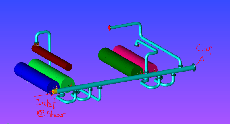
The Supply manifold feeds water to 6 Coolers, all located very close to one another. The Vendor of the Coolers has given info regarding how much water is needed (mass flow rate) for the cooling process.

Cooler 1: 245 kg/s
Cooler 2: 104 kg/s
Cooler 3: 107 kg/s
Cooler 4: 100 kg/s
Cooler 5: 80 kg/s
Cooler 6: 433 kg/s

So for each branch that connects the manifold to the respective cooler I have calculated the Volume flow rate (Q1,Q2...,Q6), and considered a maximum velocity of v=2m/s for each branch, in order to calculate their Size.

Considering Qi = v*Ai => Ai = Qi/v
Ai = pi*Di^2/4 => Di = sqrt(4*Qi/v*pi)

The sizes that I have calculated are:
Branch 1: 16"
Branch 2-5: 10"
Branch 6: 20"

Considering all these: please give me feedback regarding the procedure I have followed to Size the branches and considering those sizes are correct, how do I size the CW Header?

Thank you all in advance
 
Replies continue below

Recommended for you

What usually works is the largest branch size + 2" here = 24"

More importantly is to ensure the branch sizes are sufficient to get each branch flow to the coolers and back to the pump and chiller inlet without too much head loss.

--Einstein gave the same test to students every year. When asked why he would do something like that, "Because the answers had changed."
 
If the coolers are all close together the individual branch lines will be short and designing on the basis of velocity will give you a safe design, but you might be able to get away with smaller diameter pipes.

For example, if the line to Cooler 6 is 20" Sch 40 then the velocity would be 2.4 m/s and the pressure drop 8.2 kPa/100m. Dropping the size to 18" will increase the velocity to 3.0 m/s and the pressure drop to 14.1 kPa/100m. Check what size nozzles have been installed on the cooler and if they are less than 20" and the distance from the main is small then consider what saving you could get from the smaller line and valves.

If the header length is short then also designing it on the basis of velocity is OK, but I would definitely check the pressure drop as well. Using 1503-44's rule of thumb result of 24" would give a velocity of 4.1 m/s and a pressure drop of 18.4 kPa/100m which would be quite reasonable for a shortish (<100m) line, but if the line is 250m maybe not.

Another consideration is the relative elevations of the cooling tower and the coolers. In the days of yore it was common to have heat exchangers mounted fairly high in the buildings and the cooling water returns were open to atmosphere and driven by gravity. In those cases it was also necessary to consider self-venting flow for the vertical sections of the return line. These days exchangers are usually installed lower down in the building with pressurized cooling water circuits and the return lines can be the same size as the supply lines.

Katmar Software - AioFlo Pipe Hydraulics

"An undefined problem has an infinite number of solutions"
 
Needs a diagram, so e.g. where does the incoming water enter the header?

on the end? both ends? in the middle? two connections? Makes a big difference as does where in the sequence these offtakes are.

Worst case is in at one end.

Normally a good ROT is to sum the outlet headers square area and use the square root of that as the header size.

So in this case a 36" header. Sounds reasonable to me when you've got a 20" connection flowing at 2 m/s at the same time as 4 10" and a 16".


Remember - More details = better answers
Also: If you get a response it's polite to respond to it.
 
Rules of thumb (ROTs) are useful as starting points for iterative calculations but using them for real design is wasteful at best and dangerous at worst.

The total flowrate of 1069 kg/s in a 36" pipe would give a velocity of 1.7 m/s and a pressure drop of 2.0 kPa/100m (0.1 psi/100ft). Unless the line is very long this would be an extreme overdesign. For a given flowrate, the pressure drop for turbulent flow varies with the 5th power of the diameter. This means that you can use higher velocities at larger diameters.

Katmar Software - AioFlo Pipe Hydraulics

"An undefined problem has an infinite number of solutions"
 
It is, but equally if the manifold is quite short (3-4m long?) the saving for e.g. a 24" or 30" header is negligible.

Make it too short and strange things happens with swirl and different flow.

Split the difference and put in a 30" heeder would work for me.

Remember - More details = better answers
Also: If you get a response it's polite to respond to it.
 
If you are talking of just the manifold section where the branch pipes connect into then I am with you on the 36" section. I took it as the size for the complete header and 36" is unnecessarily big for that. But for the short section where the other branches need to be connected into having it a bit bigger makes it more practical in terms of fitting it all together.

Katmar Software - AioFlo Pipe Hydraulics

"An undefined problem has an infinite number of solutions"
 
Thank you all for the prompt replies,

The manifold will be about 25m in length, the flow comes from the one side at pressure of 5 bar and the other side has a cap. In the photo below you can see a preliminary arrangement just to get a feeling of what we are talking about. Thank you again [bigsmile]
CW_Manifold_u3cna5.png
 
In at one end is the worst case so I would go for min 30" fixed diameter.

You could get fancy and have 36" or 30" for the first 3 then reduce down to 30" or 24", but frankly just not worth it.

Why are some off the top and others off the bottom? Should all be the same to avoid any issues with air.

Remember - More details = better answers
Also: If you get a response it's polite to respond to it.
 
Where is #1 and especially #6 ?
Those 2 carry more than 2X the sum of the others.
Such Long headers are usually fed at the middle.
End feed potentially forces you to consider and avoid maximum velocities.
If those both are near the cap, a 30" might work.
If those are both at the source, 24" may be possible and too big for the rest of the 25m length.
If feed was from center, a 24" could be a reasonable choice.


--Einstein gave the same test to students every year. When asked why he would do something like that, "Because the answers had changed."
 
CW header size will depend on which set of these coolers results in max flow in this header - are all coolers running at max flow all the time ?
The sizes you've computed for each branch seem reasonable at 6fps. For these short branches, you could use up to 10fps, provided these are not copper nickel pipes.

 
Center feed does tend to minimize velocities, as it can split total flow in half immediately. It should usually be your first instinct to finding a configuration that works as well as possible. Here maybe not so much, because you have a wide variation of chiller sizes. Here maybe you need to offset the feed from center to try to balance flows to get half going to each side. Depends on your order of chiller branch lines. Or just change the branch line configurations and header connection order to get a more balanced flow. Providing it doesn't look like a plate of spaghetti when it's finished.

--Einstein gave the same test to students every year. When asked why he would do something like that, "Because the answers had changed."
 
Back
Top