Eng-Tips is the largest engineering community on the Internet

Intelligent Work Forums for Engineering Professionals

sizing short lines for gas 2

Status
Not open for further replies.

engr2GW

Petroleum
Nov 7, 2010
307
0
0
US
Hello everyone:
GAS: for short (50 to 400 feet) run of gas lines, especially in low pressure applications (50 - 150 psi), is formulas like Weymouth equation suitable if one knows the source pressure and deliver pressure (e.g. from a separator to compression suction)? or is there a better methodology?

As much as possible, do it right the first time...
 
Replies continue below

Recommended for you

Probably not the best one to use for that. It was developed for higher pressures, longer pipelines and turbulent natural gas flows.

Try Churchill, as that will work for liquids or gases, turbulent and laminar flow and even within transitional Reynolds numbers when velocities are in intermediate ranges. You are borderline at 150 psig for including a compressibility factor.

 
The short answer is yes, there are better ways to do it. Look up the isothermal equation for compressible flow in Crane or any other good fluid mechanics text.

The long answer was probably best given by Donald Schroeder. If the old fashioned equations (Weymouth, Panhandle etc) are worked backwards into the fundamental equation it shows that they do not calculate the friction factor properly. All these old equations make an approximation of the friction factor (via a transmission factor), but since the work by Colebrook and White in the 1930s and Moody in the 1940s we have the tools to calculate the friction factor far more accurately. The old equations date from around 1910 and their sell-by dates have passed.

Regarding the comments by -thirtynine: Churchill has done excellent work on correlating the friction factor, but I am not aware of him publishing an actual flow equation. It would be hard to imagine a single equation that deals with both liquids and gases (i.e. compressible and incompressible flow). The fact that Churchill's friction factor correlation generates unique values in the transition zone between the laminar and turbulent zones makes software solutions feasible, but this should not make you believe that you can make workable designs in this zone. Flow in this zone is unstable and should be avoided unless you know exactly what you are doing.

Katmar Software - AioFlo Pipe Hydraulics

"An undefined problem has an infinite number of solutions"
 
Then how do you explain the fact that Churchill tracks the historic flow equations favourites, that must be reverted to in each separate zone, so well? Is not Reynolds number calculated in the same manner for a gas as a liquid? We should remember that those old school equations, yes Moody, Colebrooke, White, were developed well before the advent of the 4-function Casio calculator. Practically speaking, you will find far more error in friction losses from your idealization vs true value of pipe roughness factors than from using Churchill or your favourite eq across transition zones. One thing for certain today is that Moody, Colebrok-White can now join the pile of old papers in the bin, because they have passed their expiration dates too.
maxresdefault.jpg


This is very difficult to solve with a 4-function machine. Try it with a sliderule and you can see it was completely out of Moody's and Colebrook's technical reach. Heck. Maybe it is easier with a sliderule, but alas, I no longer have one that I can experiment with. Well, waste of time anyway.

phpyNMhXF.png
 
Short line where pressure drop is less than 10% of inlet can be easily calculated as many either take the midpoint density or ignore it changing.

How accurate do you want to be?

Remember - More details = better answers
Also: If you get a response it's polite to respond to it.
 
If this is a rate check for an existing line, check that the compressor suction line is free draining throughout, else gas line pressure drop calcs would be invalid. Also confirm there is no possibility of wax, long chain paraffins, corrosion inhibitors bunging up the line. Separator demister pressure drop can be much higher than expected if there is wax, dirt, other fouling substances, foam, or if the vapor space between NLL (or LAH)in the sep and demister bottom is insufficient.
 
Or break into segments, each segment limited to 10% P drop.

Right. Roughness factor, fittings, bends, +++ all the other crap.
I dont need to iterate Colebrook. In field accuracies are +/- 10% for all of them.
Sometimes old pipe is smoother than when bought, after its been sand blasted for 10 years.

 
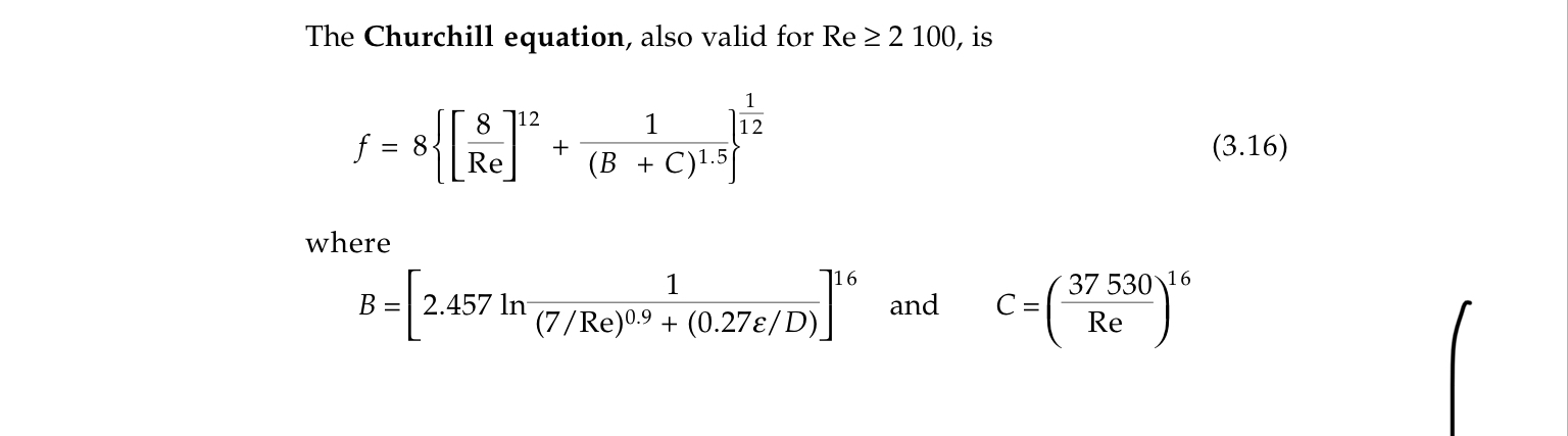
@-thirtyfive - you may think I am being pedantic, but I feel that it is important to distinguish between the calculation of a friction factor and the calculation of a flow rate or pressure drop. The Churchill equation is not a flow equation. It is a correlation for estimating the friction factor. The friction factor can then be used in the Darcy-Weisbach flow equation for incompressible fluids, the isothermal or adiabatic flow equations for compressible fluids, and a whole host of flow equations for two-phase gas-liquid flow.

It is very important not to be deceived into thinking that because the Churchill equation gives unique values for the friction factor in the critical zone between the laminar and turbulent zones that they are real usable numbers. The fact that the equation gives unique results is important in computer solutions - I have taken advantage of this myself in my AioFlo software - but as engineers we must be aware of the dangers of designing in the critical zone.

Here are some quotes regarding the friction factor in the critical zone:
From Churchill's 1977 paper - "The various sets of experimental data for the transition regime between laminar and turbulent flow are quite scattered."
From Coulson and Richardson Vol 1 - "Reproducible values of pressure drop cannot be obtained in this region."
From Rennels and Hudson - "For pipe Reynolds numbers between 2100 and 3000 to 4000, the friction factor can have large uncertainties and is highly indeterminate."

Fortunately in gas flow it is very unlikely that laminar or critical flow will be encountered.

It is a pity that the friction factor charts in the old Moody and Colebrook-White papers are no longer used. There is too much time pressure on engineers these days to get results out quickly and we don't have time to plot points on the charts anymore, but there is a great deal of understanding to be obtained by knowing where on the chart (and how close to the transition points) we are working. I suppose this is the price of progress.

Some clarification on the 10% rule that was mentioned by several posters above. This refers to the practice of using the Darcy-Weisbach equation, which strictly speaking is for incompressible flow only, for gas flow provided the pressure drop is less than 10% of the absolute upstream pressure. In my experience using this rule of thumb does give reasonable results, but with computerized methods available to do it properly there is not much point in doing this. It was helpful in the days of slide rules, and even with 4-function calculators, but it can also be relegated to the scrap heap now.

Katmar Software - AioFlo Pipe Hydraulics

"An undefined problem has an infinite number of solutions"
 
Why is that important.

The first term looks vaguely like friction factors of old. The others are transitional factors. The important thing for me is that it works to find pressure drop of liquids and gases. I dont much care if it does that by using a friction factor somewhere in there or not. I'm happy thinking it is a simple black box.

Neural networks, after some training, are pretty adept at finding pressure drops too. They do so without any clue of what a friction factor is at all. I predict that friction factors will disappear as soon as Nural networks take over the world..


Dont throw the 10% rule into the bin just yet. Even the best pipelne flow analysis software on the market today use a variation of that technique. They automatically and internally break down each pipe segment into very short subsegments when analyzing not only gas streams, but also do the same for liquid flows. The subsegmentation process continues to use shorter and shorter lengths, checking the results against density and viscosity, compressibility, fluid composition and other properties of the stream that vary with pressures and temperatures or position along the pipeline, until any residual errors are less than a user specified tolerance, such as 1 psi. Unfortunately they , to my knowledge, still use antiquated Colebrook iterative friction factors, which increase calculation times, but with faster computation cycles available these days, nobody has bothered to change them. Some do not even bother with doing correct calculations by selecting proper friction factors in the laminar flow regions, because pipelines never go there and the final results generated are still within practical margins of error anyway. The user is allowed to specify more accurate pressure drops in segments that might experience problems with laminar flows in that regard.


OP - outside of having any software to do this for you, I recommend using the IGT Equation (the Improved IGT Equation if you can find it online anymore). An efficiency of 85% is conservative. I recommend this equation because it is relatively easy to calculate by hand. It also is fairly accurate in a moderate Re number range. If you have high or low Re, there are better equations.

In addition, I would check the velocity at the inlet pressure. Then once you run the equation, and determine the outlet pressure, check the velocity at the outlet. This should give you a decent “gut check”. If the gas is screaming through the line, the pipe is too small. If it is barely moving, the pipe is too large.
 
How do you know if its too high or too low? The object is almost always to calculate flow (or maybe P_drop), but you are effectively saying that I have to have knowledge of the flow rate and calculate f? That's a switch. I dont recall anyone ever asking me to calculate the "friction factor" since my fluid mechanics class at university in 1973.

 
Based upon my experience, which is to say verifying actual data in the field to calculated results, the IGT with 85% efficiency provides a conservative estimate (will slightly under predict flow or over predict pressure drop) - when properly applied (ie used under the operating parameters that the equation was derived).

The problem with all the equations is determining f (if it is required). Colebrook’s f is an iterative equation, and it is really isn’t feasible to do by hand. The IGT does not use a friction factor and thus has that as an advantage for hand calculation.

All of the equations have their pros/cons, and the professional should determine which equation is best. The IGT equation with efficiency factor will produce decent results for moderate pressures and flows.
 
No. No. No. It appears that you do not have much experience with Colebrook, or you would know that it is very much possible to solve with nothing more than a 4-function calculator and that it requires no more than 3 iterations to get a friction factor accurate enough for any practical need. With Excel, that "iteration" can easily be accomplished by using a recursive formulation, taking up only 1 cell and without resorting to use of GoalSeek, Macros, or VBA.
 
Once again, it gets back to "how accurate do you need/want to be". Based upon your own estimate, hand calculation of the Colebrook is at least 3 times as long due to the iterative. If you have a lot of these to do, that is going to add a considerable amount of time.

The excel is a good idea, if it is already programmed/the OP has sufficient experience programming it.

You prefer the Colebrook, I prefer the IGT. To each his own - it would be interesting to do a test calculation between both methods and compare the results:

400 LF with 50% allowance for fittings(600 LF w/ fittings) of 12" sch. 40 pipeline. 100 psig inlet. Temp base = 520R. Pressure base = 14.7 psia. Tactual = 540R. Z = 0.98. SG = 0.6, viscosity = 0.000008 lb/ft-s.

IGT w/ 85% efficiency: at 95# outlet pressure; flow = 2,940,443 SCFH. Note it took me roughly 5 mins to calculate that by hand.
 
Status
Not open for further replies.
Back
Top