Continue to Site

Eng-Tips is the largest engineering community on the Internet

Intelligent Work Forums for Engineering Professionals

  • Congratulations MintJulep on being selected by the Eng-Tips community for having the most helpful posts in the forums last week. Way to Go!

Slab-Brick wall slip joint robustness/lateral load transfer

Status
Not open for further replies.

Enhineyero

Structural
Sep 1, 2011
284
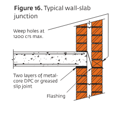
The typical detail for a concrete slab bearing on clay brick wall involves a slip joint to accommodate horizontal movement (due to brick growth/ concrete shrinkage). I understand this, however, how do you transfer earthquake/wind forces to the brick wall? How do you comply with robustness (1.5% of gravity load as a tie force) requirement?

image_voqxvk.png
?
 
Replies continue below

Recommended for you

I've never seen that detail, but we stopped using load bearing multiwythe brick walls in this region 90 years ago. I'm interested to hear what others might have to say.
 
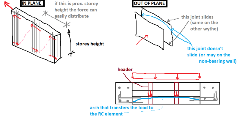
I'd expect something like the picture below to happen (I haven't seen it anywhere, just what I'd expect).
This picture is for either reinforced or confined masonry.
masonry_n4tnmk.png

IN PLANE the vertical reinforcement is continuous (it connects with the slab, at least where I'm from). It can either be in a confining RC element or a strong band made with special brick filled with grout (I'll call it all "confining element" in the rest of my post). This reinforcement is like a column (I didn't draw stirrups for clarity, they may not exist always) and in Europe the distance of vertical bands may not be more than 4 meters which means that the diagonal strut can be utilized nicely for regular storey heights.

OUT OF PLANE it depends on some construction details (on my picture with blue I mentioned that vertical joint may be sliding in non-bearing wall, I meant WYTHE... that's in case that no horizontal reinforcement for connecting with confining element exists in that wythe). The force travels through header bricks to the bearing wythe and from it to confining elements. I wouldn't count on vertical load transfer on the internal wythe because of sliding you mentioned.
EDIT: Sorry, the outer wythe doesn't slide on a horizontal so it may transfer the load in a vertical direction, it all depends on the placement of the header elements I guess.

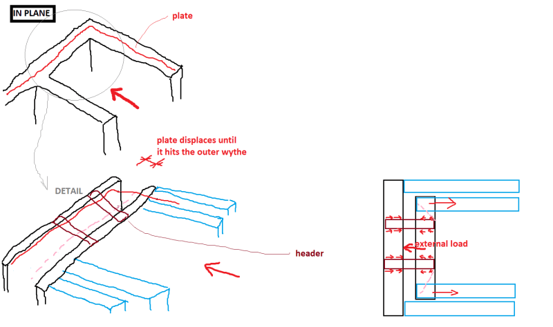
For unreinforced masonry I'd expect the following picture to happen (I just drew in plane behaviour which basically includes the out of plane component).
unreinforced_gmdqzs.png


Basically what I think will happen here is that the slab will hit the outer wythe which will then form a series of arches between headers, each of which will transfer the load to the other side by joint shear. When the load transfers to the inner wythe it'll form an arch that transfers it to the wall parallel to the applied load. In order for this to work, perpendicular walls need to be connected (at least the bearing wythes).

EDIT: Note that if for example you have a whole horizontal line of headers the load will probably transfer in the vertical direction when loaded out of plane (outer wythe), while if the headers are dispersed the load will travel quite differently... that's why I didn't really draw the load path to or from headers, that's structure specific I believe.
 
@hardbutmild - your approach sounds a bit complex.

I think that movement of the slab towards the weak axis of the wall will be allowed by the slip joint (avoiding any outof-plane moment). I'm not sure if slip joint is effective for slab movement parallel to the strong axis of the wall.
 
...however, how do you transfer earthquake/wind forces to the brick wall?

You don't. At least I've never seen it done in anything (other than residential) for anything designed since about the early 90's.

With such a detail, I would expect the wythes of brick to sandwich a reinforced concrete [RC] wall and the slab/RC wall ties being made to each other.
 
How do you comply with robustness (1.5% of gravity load as a tie force) requirement?

The slip joint is only required on one end of the slab to relieve the stress due to shrinkage, it shouldn't placed on both ends, which will create unstable condition.
 
After a bit of digging, found the answer. For those who are interested, slip joint will be able to accommodate small movements (i.e. shrinkage/brick growth) but has enough friction capacity for larger movements (i.e. Earthquake/wind). Code has a 'shear factor' for slip joint of 0.1, as a comparison mortar bed joints has a factor of 0.3
 
So this method is essentially to reduce the lateral load capacity to control the crack. It does not rest very well, as shrinkage crack might still occur at lower level friction, but at the expanse of reduced load capacity and added cost of joint material and laboring. Why not just use more well spaced reinforcement to control crack width to achieve the same goal, but much simpler.
 
r13 - thanks for your thoughts, the detail is mainly to allow small movements to the slab/wall interface and minimise out-of-plane loads to the brick wall. Its a brick wall with a cavity, unlikely to place reinforcement there.
 
The reinforcement is to be provide in the slab to control crack width. I understand the slip joint will allow some movement before transfer the lateral load to the wall. Thanks for the clarification.
 
Status
Not open for further replies.

Part and Inventory Search

Sponsor