Continue to Site

Eng-Tips is the largest engineering community on the Internet

Intelligent Work Forums for Engineering Professionals

  • Congratulations KootK on being selected by the Eng-Tips community for having the most helpful posts in the forums last week. Way to Go!

SLOPING BEAM FORCES AND MOMENTS FORMULAE

Status
Not open for further replies.

gmannix1000

Structural
Dec 6, 2010
21
Hi All,

Simple question - roof beam sloping and I just want to double check that I'm calculating the shear, moment and axial loads in the member correctly. See attached for formulae that I am arriving at.

Obviously, let's say the snow and the dead load of the member will act vertically so the UDL on the beam will be wCos(a), with (a) being the angle of the beam. Thus, the axial component of this will be wSin(a), then times the length of the beam, correct?

Also, if this becomes a two span beam, I'd imagine the axial force formula wouldn't change, just the moment and shear formulae?

Is this the correct way of analysing this?

Thanks so much, working myself into a tizzy over this, needlessly no doubt!
 
 http://files.engineering.com/getfile.aspx?folder=a48cb77e-7969-4d37-8dde-98826ba4f3e6&file=Sloping_Beam.pdf
Replies continue below

Recommended for you

I just always project it on a horizontal plane. Assuming your load is all vertical (and projected horizontally): the formula would just be wl[sup]2[/sup]/8, but your "l" to use in that formula would NOT be the hypotenuse of the right triangle formed.....it would be the length of the horizontal portion.
 
Here is something from a textbook that I have implemented into beam and frame spreadsheets. I have found it pretty helpful. w_hat_x is the axial distributed load per local coordinates. w_hat_y is the transverse distributed load per local coordinates. I think that your equations are correct if you are talking about the self-weight of a member (the 2nd situation described in the attached text), but might need some modifying for something like a snow load as you have drawn in your schematic (see the 3rd situation described in the text). Hope that helps.
 
 http://files.engineering.com/getfile.aspx?folder=62e4bee8-15c5-4f57-84cd-cda87c7f6455&file=Roof_Frames_-Rick_Balling_Text.pdf
you can project the structure onto a convenient plane for the load (ie horizontal for vertical load), so that the depth of the section increases (by 1/cos(slope_angle).
or you can project the load into the beam axes, which would reduce the normal load, by cos(slope_angle), and give the beam an axial load component.

humm ...

another day in paradise, or is paradise one day closer ?
 
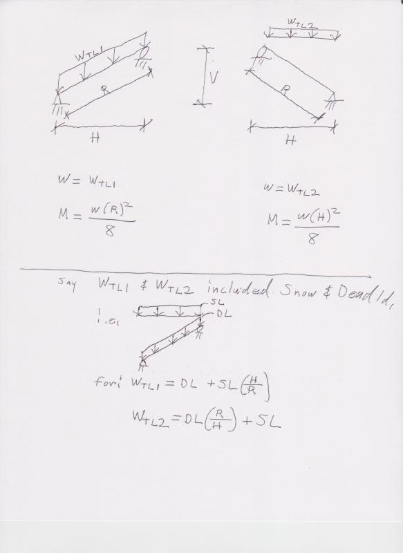
In the pic, I elaborate a bit further. (Sorry if it appears sloppy.)

3.8.18_001_hwgnnz.jpg


[red]EDIT:[/red] WTL1 above should be multiplied by H/R for the purposes of moment calculation.
 
The moment of a sloping beam of length L is the same as that of a horizontal beam of length H = L.cosθ. If W is the total gravity load on the beam, M = WH/8. If deflections are required, the sloping length L must be used along with the normal component of W.

BA
 
Hi All,

Thanks so much for your inputs.

WARose - I think WTL1 should be drawn perpendicular in your first sketch above, if R is the length being taken, right?

For Member self weight, I agree.
For finishes (e.g. roof tiles/slates and loads are on the global axis), I still need to multiple this my Cos(a) to get the load perpendicular to the beam - just like snow, correct?

rb1957 - What is the axial component if I multiply the snow and dead loads by Cos(a) to obtain a UDL perpendiculat to the beam, and taking the hyprothenuse as the length of the beam?

Thanks guys!
 
Your normal component (W cosθ) is correct. However, it has to be adjusted by a factor of H/L (i.e. W gets reduced because it acts over a longer length L compared to H).
H/L = cosθ.
Therefore, load normal to beam's local axis would be W * (cosθ)[sup]2[/sup]
And Moment would be W * (cosθ)[sup]2[/sup] * L[sup]2[/sup] / 8

W * H[sup]2[/sup]/8 = W * (cosθ)[sup]2[/sup] * L[sup]2[/sup]/8
H = L cosθ

Another good resource.
 
WARose - I think WTL1 should be drawn perpendicular in your first sketch above, if R is the length being taken, right?

Correct. Perpendicular to the span (at least for the purposes of moment calculation). That means WTL1 should be multiplied by H/R.

Good catch.....I will update my post above to note that.

If you have Bryer's book on wood design.....he goes through this. (I think very effectively.)

 
is the load normal to the surface ? what's the difference between wt1 and wt2 ?
it looks to me as though wt1 normal to the surface (maybe a component of a down load) and so moment would be xR
and wt2 is the vertical component and moment would be xH (the horizontal component of the sloping roof).

cos^2 looks odd to me ... I can see cos as either the projected length or the projected load, but not cos^2 ??


another day in paradise, or is paradise one day closer ?
 
what's the difference between wt1 and wt2 ?

WTL1 is part of the "sloping beam method"; WTL2 is part of the "horizontal plane method". (The latter being more popular in wood design.) WTL1 is drawn correctly, but I forgot to note you need to take components to plug into the moment equation. Also, calculating the shear (i.e. wl/2) with WTL2 will give you a conservative result (higher than the actual value).
 
so the moments would be (W*cos(theta))*R or W*(R*cos(theta)) ?

another day in paradise, or is paradise one day closer ?
 
rb1957 said:
so the moments would be (W*cos(theta))*R or W*(R*cos(theta)) ?

The moment is W*R*cosθ/8 where W is the total gravity load on the beam and R is the sloping length of the beam. This is the same as W*H/8 where H is the horizontal span.

BA
 
so "load normal to beam's local axis would be W * (cosθ)[sup]2[/sup]" is wrong, but the later cos^2 terms are due to L^2 ... makes sense.

another day in paradise, or is paradise one day closer ?
 
slickdeals had it right, but he is using upper case W to represent uniformly distributed load (UDL) whereas I am using upper case W to represent total gravity load on the beam.

If we define lower case 'w' to represent UDL per unit length of horizontal projection and upper case 'W' to represent total gravity load on the beam, then:

1. M = wH[sup]2[/sup]/8
2. M = w(Lcosθ)[sup]2[/sup]/8
3. M = WH/8
4. M = WLcosθ/8

are all equivalent expressions for moment


BA
 
ok, I see it now

another day in paradise, or is paradise one day closer ?
 
See page 4 here:

gmannix1000 said:
Thus, the axial component of this will be wSin(a), then times the length of the beam, correct?

I think joist mfrs assume the axial component is resisted by the diaphragm even though the joist is stable without this assumption since there would still just be a vertical reaction at each end of the joist without the diaphragm assumption. They would then not design the joist for the axial component. A lot of engineers probably also assume this with beams and diaphragms. I don't 100% agree with this.
 
Status
Not open for further replies.

Part and Inventory Search

Sponsor