Eng-Tips is the largest engineering community on the Internet

Intelligent Work Forums for Engineering Professionals

Small Hydraulic Proportional Valve

Status
Not open for further replies.

gr3ggh3ad

Mechanical
Dec 5, 2022
4
0
0
US
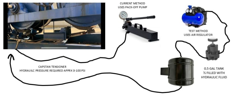
Hi - The goal of my project is spool high-strength wire on to a drum at a fixed tension. To do so, I am considering controlling a small, hydraulic proportional valve using a PLC that will essentially feed a hydraulic brake. I will have a 4-20mA input (line tension feedback) to a programmable controller , a display to enter my setpoint (desired line tension), then vary the hydraulic valve output accordingly to control pressure only (no flow... the pressure output will feed a hydraulic brake to adjust line tension). The max pressure is probably less than 500 psi. I do not have a ton of experience with hydraulics, however I do have experience with PLC controls. I am mainly looking for help in pointing me toward a proportional valve that will meet these requirements, but any other tips or knowledge of a small PID controller that will do the job would be appreciated, too. Also, if you have a lead on a small scale hydraulic pump to feed the valve, please let me know as well. Thanks! Gregg
 
Replies continue below

Recommended for you

This is what i could get from what i understand of the application. The pressure can be varied from 15 to 5000psi using a 0-10V or a 4-20mA signal. You write a code in the PLC for the scaling between the strain gauge input and the signal output to tune the PID.


I have some experience in similar applications but using pneumatic proportional pressure control valve not hydraulic.So, check this thoroughly.
 
The valve described by gr3ggh3ad will work if the rest of the system is good.
Is this a new installation?
Normally one controls the tension by controlling the torque on the winder. Also, you need something to lay the wire smoothly back and forth on the spool/drum. Nothing is said about the source of the wire. Sometimes there is a tension loop between the source and destination spool.
There are electric winding machines that cost less than the valve and machine is put together.
There are many such machines. I would look around and see if you can buy something off the shelf before trying to re-create the wheel.
BTW, I sell motion controller that have done applications like this but the reason why our motion controller was chosen is because they were winding very thick copper that was rectangular in shape so a custom machine was necessary. Unless you are doing something that is not normal you should look for something off the shelf.


Peter Nachtwey
Delta Computer Systems
IFPS Hall of Fame Member
 
I think you need to vary the air pressure over a hydraulic chamber or piston and not the hydraulics itself as you have no flow.

Look up how automatic car brakes work?

Remember - More details = better answers
Also: If you get a response it's polite to respond to it.
 
Thank you all for the replies. Forgive me as this is my first post... I do not see a way to reply to individual responses, only 'reply to the post'. Allow me to clarify my scenario:

We have trucks with 15K+ feet of wire spooled on for oil, gas, and geothermal well service work. Occasionally we spool new line [under tension] on the trucks. Our current method is open-loop: an operator has one hand on a pack- off pump which applies hydraulic pressure to a capstan brake [to vary the tension], and an eye on the line-tension display. If the line tension decreases, he pumps the pack-off pump to increase the drag at the capstan. If the tension increases, he bleeds off a little pressure to reduce the tension.

I want to automate this and make it closed-loop. I'll fabricate a portable box that we place at the truck when spooling new line. I'll use a 4-20mA output from the line-tension sensor on the truck and bring it into the 'box' as my feedback. A small display on 'the box' will allow the operator to enter the setpoint (desired tension). The 'box' will have small hydraulic pump, and a variable valve to control the pressure out to the brake on the capstan; I think this should keep the line tension fairly constant.

I know enough about controls to make it happen [in theory]... I just do not have the hydraulic experience to choose a valve.

Thanks again!
 
As LittleInch suggested, readily available solenoid valves (even proportional ones) are not very good at controlling pressure directly. To a first approximation, what they control is flow (and, if you haven't got some sort of mechanism for maintaining a constant pressure drop across the valve, even that's a pretty poor approximation).

Here are two approaches you might try.

You could connect a single direction valve in series with a fixed orifice and tap off the pressure at the junction between them - the hydraulic analogue of a potentiometer. This approach can be made to give you something that responds very quickly, but is wasteful of energy.

The other is to use a bidirectional valve to charge or discharge an accumulator - much more analogous to your existing approach. Although the response is slower, pressure control will be smoother and you might even get away with bang-bang control rather than a proportional valve.​

However, making your chosen valve control pressure is only the start of the job. You've still got to sort out how your valve arrangement is going to get a suitable and reliable supply of hydraulic fluid. It isn't enough just to clag in a small hydraulic pump, switch it on and then turn the tap on and off. To a first approximation (Peter will tell you how misleading this is, but for a first approximation, it will do), cheap hydraulic pumps are constant flow devices. That means that when your valves aren't demanding flow, you need to choose a suitable place for that constant flow to go (suitable doesn't mean out through a new hole in the side of the pump). In the motion-control world, it's common to find that the proportional control valve that does the simple job you wanted in the first place ends up supported by six or seven additional valves and a handful of orifices - without which the system will overheat, self-destruct, refuse to work, or some combination of the three.

If a handpump and bleed valve worked well enough in the first place, perhaps you could just replace the handpump with a small electrically driven pump with a check valve on the output and then only run the motor when you need to increase pressure. Replace the bleed valve with a solenoid valve and an orifice to limit the flow. Add an accumulator if you want to slow the process down.

A.
 
zeusfaber (and littleinch) - The lightbulb went on. I get it now that it would be difficult to control the pressure directly with hydraulics. The idea of air pressure over the hydraulic chamber makes perfect sense. Now I need to find out how I can regulate the air pressure with a controller. Thanks again!
 
Hello,
It's easy to regulate the hydraulic pressure. If you gave more details on the current hydraulic circuit and on the brake, the answer would obviously be more appropriate.
If currently your pump runs constantly and it does not heat the oil too much: then you are using a proportional pressure relief valve. example: RZM Atos; DBE Bosch rexroth; PDB Hydac
If the pump stops and there is an accumulator then use a proportional 3-way pressure reducer. example: ZGO Atos; DRE Bosch rexroth; PDR Hydac
Cordially
 
Depends on your hydraulic pressure on the brake really.

You could do this with a two stage hydraulic accumulator system as well - high pressure supply into a decent sized accumulator so you pump it up and leave it. Solenoid valve with a flow control set by you ( needle valve) into a second hydraulic system connected to your brake with a small accumulator with a return path to a reservoir via a second solenoid valve also with a small needle valve. Then your PID loop either opens one valve for more tension or opens the second for less. Then all you really need to control or measure is the tension which you increase or decrease as required to maintain your set point.

You might find something like this where you can vary pressure via a 4-20, but if you want to build it yourself then the option above might be worth looking at, but this really mirrors your current system, just via a PID loop.

Just an idea.

Remember - More details = better answers
Also: If you get a response it's polite to respond to it.
 
Again... thank you for the input.

The attached image [below] shows the basics of the existing set up: the brakes on a capstan are currently being controlled with a hand pack-off pump; the greater the pressure on the brakes, the greater the capstan causes tension on the line being pulled around it. The hydraulic pressure required to obtain the tension I want is only on the order of 50-100 psi.

The second part of the image shows my proposed test. I bought a precision, relieving regulator (0-150psi) and 0.5 gal tank good for 200 psi. I'll fill the tank approx. half full of hydraulic fluid, then use the air regulator to vary the pressure over the hyd. fluid, which varies the brakes, which varies the tension on my line as I am spooling it onto the truck.

If this works well enough, I'll leave it with just the regulator [open loop]. If it really well and we want to go to the next level, I'll get a small PID controller and an Electronically Controlled Precision Compressed Air Regulator like this one from McMaster Carr and attempt to do it closed loop. (https://res.cloudinary.com/engineering-com/image/upload/v1671231877/tips/CAPSTAN_PRESSURE_DIAGRAM_smguim.jpg[/img]s/maximum-pressure~100-psi/regulator-style~relieving/]Link)

CAPSTAN_PRESSURE_DIAGRAM_pl01em.jpg
 
That should work. The reaction time might be a bit slower than the hydraulic oil version but that might be a good thing?

Let us know how it goes.

I thought you might need more than 100 psi but that's well within a simple air compressor range.

Remember - More details = better answers
Also: If you get a response it's polite to respond to it.
 
Status
Not open for further replies.
Back
Top