KennyRogers
Structural
Morning all,
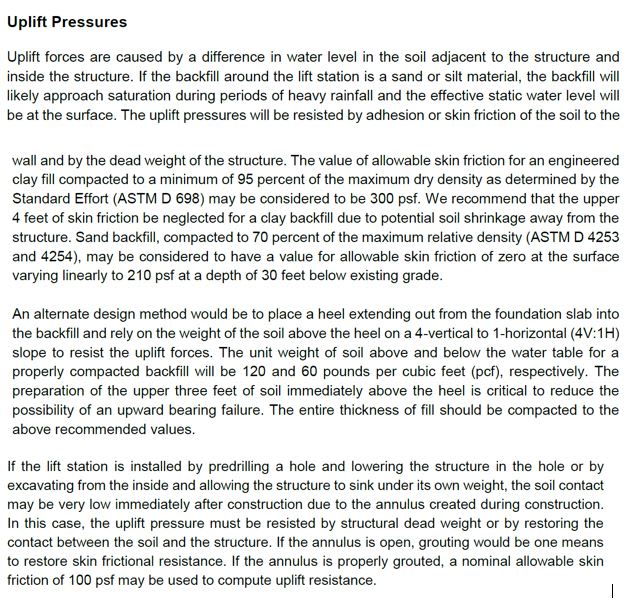
I have an underground tank we are looking at for rehabilitation. I am concerned about uplift due to buoyancy from a relatively high water table. With the all of the gravity/self weights, I am coming up shy on balancing the uplift forces. I was considering taking into account the effect of soil friction on the vertical walls of this tank to help with resisting uplift. Does anyone have input if this has ever been used? It seems reasonable to assume that the soil friction will provide some benefit.
In terms of the analytical frictional force, I was considering taking the at rest soil pressure acting horizontally on the walls and computing a friction force based on the soil coefficient of friction (from tanδ, about 0.30). Since the water table is relatively high, I was going to use the effective stress to compute the lateral earth pressure at locations below the water table. These are clay soils and I was thinking about adding a cohesion component, however since the uplift would be a long term effect, I don't think this is an undrained analysis case. I will however check with cohesion only since there may be some short term effects, which would then transition to long term sustained loading.
To me this seems like a reasonable approach, but wanted to bounce this off someone else. Unfortunately, there aren't too many geotech savvy folks here.
When considering gravity loads only, we would only need to drop the water table about 1.5 feet. I figure we could pump water to draw down the water table, but this presents other issues with where to discharge. The water table was measured this winter, so I am thinking it could have been a relatively high (wet, warm winter) water table, but I am thinking spring could cause it to rise further. If it was late summer, I think we'd have a chance the water table would drop enough to not cause worry.
Thanks!
Kenny

