Eng-Tips is the largest engineering community on the Internet

Intelligent Work Forums for Engineering Professionals

  • Congratulations waross on being selected by the Tek-Tips community for having the most helpful posts in the forums last week. Way to Go!

Solving Portal Frame Using Slope Deflection Equations

Status
Not open for further replies.

Tygra_1983

Student
Oct 8, 2021
111
0
0
GB
Hi all,

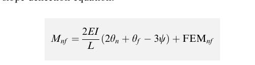
I am trying to solve the following Portal Frame:

portal_frame_pz6kgo.png


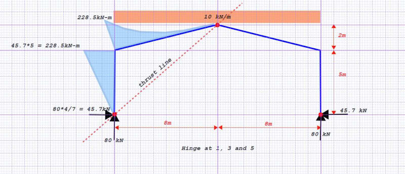
I am using BeamGuru to validate my hand calcs and they give the respective moments that are shown in the image.

The dimensions are: columns 5 metres high, and rafters that are 8.2462 metres long. The frame is 16 metres long (8 metres halfway). The peak of the frame is 7 metres.

However, when I do my hand calcs I am getting very different results and I don't know why.

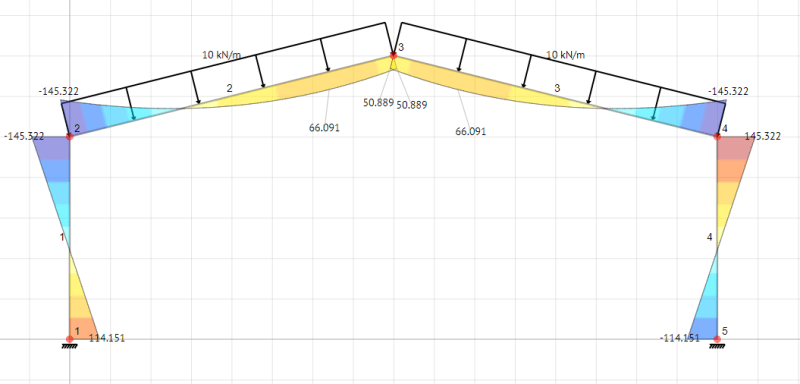
Here are my calculations in Octave:

Screenshot_17_mrwv6n.png


As you can see, I am getting moments at joint 2 of 35.227 kNm. This is way off the results in BeamGuru. I cannot see what error I am making. So could someone please help?

Many thanks!
 
Replies continue below

Recommended for you

can't read your script. How are you accounting for the redundancy (in your hand calc) ?

"Hoffen wir mal, dass alles gut geht !"
General Paulus, Nov 1942, outside Stalingrad after the launch of Operation Uranus.
 
clearer (easier to read) but I can't read (understand) python ... so let someone else have a go.

"Hoffen wir mal, dass alles gut geht !"
General Paulus, Nov 1942, outside Stalingrad after the launch of Operation Uranus.
 
looking at your joint equilibrium ... M12+M22 = 0 ... without knowing what these terms are (???) but looking at the pic above, should it be M12-M22 = 0 ?

does M12 = M22 ?

"Hoffen wir mal, dass alles gut geht !"
General Paulus, Nov 1942, outside Stalingrad after the launch of Operation Uranus.
 
What I learned at Uni is the internal equilibrium equations at the free joints (where these joints have non zero displacements/rotations), the sum of the moments equals zero.

And yes, M12 = M22. You can see this in the BeamGuru diagram. It's just BeamGuru calculated M12 and M22 as -145.322 kNm each; I'm getting 35.277 kNm.
 
on a quick cursory review it looks like you are missing the psi components of the joints to account for the fact that this frame can experience sway:
Capture_wqx6qk.jpg
 
if M12 = M22 then M12+M22 .NE. 0. Your equilibrium equations are driving M12 = -M22, no?

"Hoffen wir mal, dass alles gut geht !"
General Paulus, Nov 1942, outside Stalingrad after the launch of Operation Uranus.
 
Let's assume the frame is a three hinged arch...hinge at 1,3 and 5 (big red dot). The structure is statically determinate and it is easy to calculate the moment at 2 to be 228.5 (I took the load to be gravity load, not sloping as shown on the OP sketch).

Capture_zcikpw.jpg


The so called "hand" calculation provided is not easily understood, at least not by me. The slope deflection method would not be my choice, but it is a perfectly sound method. Since the structure and the loading are symmetrical, consider half the structure (from point 1 to 3). Rotation is zero at points 1 and 3. Horizontal deflection is zero at point 3.

Calculate rotation and deflection at point 3 with only the fixed moment at point 1. Apply horizontal force H and moment M at point 3, then solve to bring theta 3 and delta 3 to zero.

Another method, if you just want to know the answer, is to consult the book by Kleinlogel, which considers several different kinds of load on a gable frame.
 
Thanks, BAretired. I have however solved the portal frame with pinned supports using the unit load/virtual work method. I was very happy, but then when I added a lateral load (to simulate wind) I quickly realised that the frame could not take it, and there was massive horizontal deflections - because the pinned supports don't resist the rotation. Similarly, once I solved this problem I was going to add a lateral load.

I think Celt83 pointed out the problem. I was not including the psi terms from the slope deflection equations. I have only ever analysed structures where psi is zero. I had a look into it yesterday, but I think I might as well stick to using the direct stiffness method, as its quite complicated to find psi for this particular structure.
 
A three hinged arch is more flexible than a rigid gable frame, but the deflections are not "massive". Not many engineers would consider the columns fixed at the base. They are not hinged either, so perhaps a rotational spring would be ideal.

For purposes of a homework assignment, a fixed end can be assumed. I would agree that the stiffness method is best in a work environment, preferably with the aid of a computer. To perform a true hand calculation for this frame is onerous and likely to result in arithmetic errors.
 
Status
Not open for further replies.
Back
Top