Eng-Tips is the largest engineering community on the Internet

Intelligent Work Forums for Engineering Professionals

SOME QUESTIONS REGARDING SHEET METAL 4

Status
Not open for further replies.

elinah34

Mechanical
Aug 19, 2014
115
0
0
IL
Hello,

I decided to read about sheet metal design and manufacture principles for improving my design.

I have 2 questions I will be happy to be given answers to:

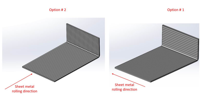
1. Bending orientation direction.
In which case I can afford a larger minimum radius?
1_poas14.jpg


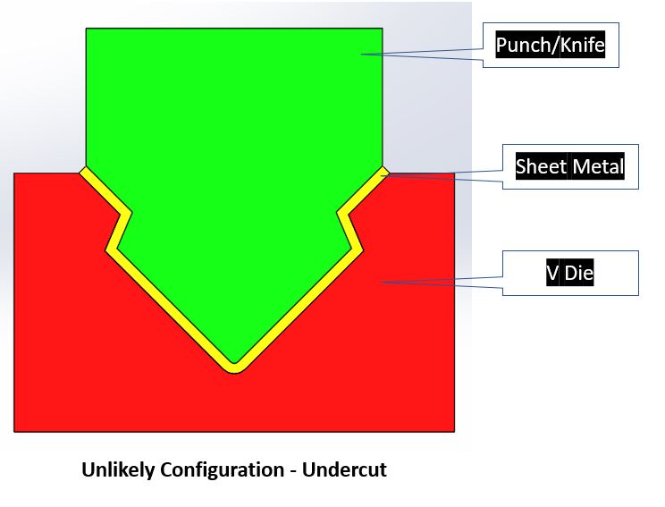
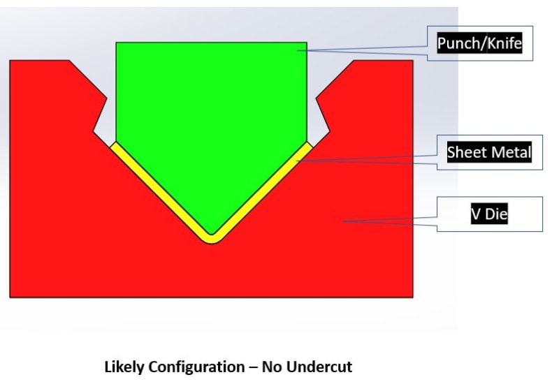
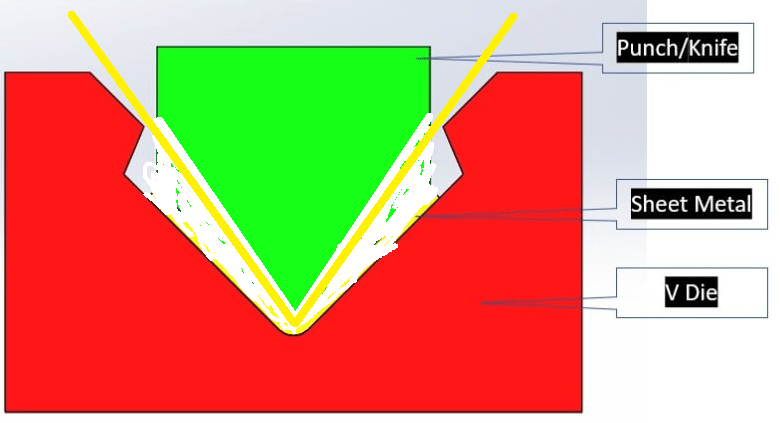
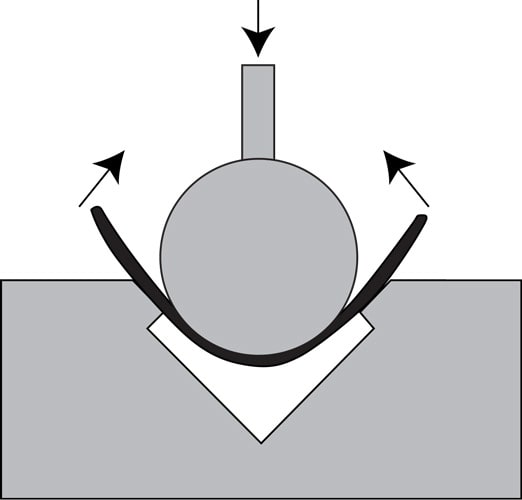
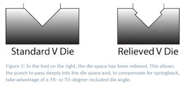
2. Second question is regarding spring back and special tooling for coping with it.
I encountered this tooling, and I am not sure how it exactly works for coping with the spring back.
2_i4rvdw.jpg


Thank you!
 
Replies continue below

Recommended for you

For your second question... the extra little jags at the top of the die cause the sheet to bend more tightly when pressed into the die (the sheet bends to, say, 78 degrees while in the die), whereupon the springiness of the metal causes the metal to release a bit once the die pressure is released (back to the desired 90 degree angle).

Dan - Owner
Footwell%20Animation%20Tiny.gif
 
The stronger the material the more likely that direction matters.
In sheet that has been normalized (or annealed) after rolling the direction should not matter.
In sheet that is cold rolled to reach higher strength (or rolled and aged) then it really does matter.
The springback in the two directions will be noticeably different in that material.


= = = = = = = = = = = = = = = = = = = =
P.E. Metallurgy, consulting work welcomed
 
elinah34,

In many years of sheet metal design, I have never specified the grain direction. Consequently, grain direction does not affect my bend radius. If your structure is heavily loaded and critical enough that grain direction and bend radius matters, you should be able to do calculations to work out the radius.

In general, when I design a bent sheet metal part, I check the material handbooks to see the minimum recommended bend radius, and I call the shop to find out what their tooling does. They can "bend in air" and get any radius you want, but the process is expensive and inaccurate. I specify very sloppy tolerance on my bend radii. I want the shop's favourite tool to work. Almost certainly, there is something in the sheet metal part that is way more important than the bend radius.

If you are the designer, spring-back is your fabricator's problem, not yours. Let them worry about it, and don't design 360[°] wrapped parts.

--
JHG
 
MacGyverS2000
Thanks for replying.
I am not sure I understand how the Relieved V Die works.
If I look at the Unlikely option, it seems useless and impossible:
1_hhuaqi.jpg

If I look at the likely option, it seems that the special design of the Relieved V Die upper features are meaningless:
2_ve7oda.jpg
 
The "Likely Configuration" should show the sheet metal extending outside the die. If there was a link to the original diagrams that might also include an explanation.
 
EdStainless
So according to your answer I understand that in option number 2 (see the original post) the bending radius might theoretically be smaller than the second (perpendicular) bending direction.
 
Take your "likely configuration" and increase the angle of the punch so that the punch angle is smaller than the die angle (say, 10 degrees smaller). Now draw your yellow sheet to run from the die center to the nib point and continue outward from the die. The angle the sheet makes while pressed may be, say 85 degrees... once the punch is released, the springiness of the sheet will pull it back towards 90 degree. No undercut is ever formed.

EDIT: You can even have the die be nearly as wide as the nib opening, which can provide a bit of "channel" in the final corner shape, but you'll need to support the sheet outside of the die so the nibs provide a bit of back angle.
Punch_d46ool.png


Dan - Owner
Footwell%20Animation%20Tiny.gif
 
Yes, in your pictured Opt #2 (where the bend is transverse to the rolling direction) you will need a bit more force but the material will likely tolerate a tighter bend radius.
The best practice is to design all of the bends with the radius that you can use in the worst case. Then not worry about orientation.
If you are working with thick and/or high strength you will have to design each bend individually.

= = = = = = = = = = = = = = = = = = = =
P.E. Metallurgy, consulting work welcomed
 
Thank you all,
I do design all the bends to have the same radius, but I really wanted to understand the limitations and constraints of the design and to sum it up.
I usually try to understand where the constraints (listed in the design tables) came from before using it.
 
By the way, if someone has a good detailed and profound article that mathematically explains how the minimum radius is calculated, it will be great. I am interested to better understand why there is a difference in the 2 perpendicular directions. I do understand why there is a difference in the required bending force, but still not sure why there is a difference in the minimum radius.
 
I may be stating the obvious, but bending parallel to the grain direction of the material (Option #1 image in your first post) can cause cracking on the outside of the bend if the bend radius is too small. Avoiding this cracking largely (maybe wholly) drives minimum bend radius, at least when bending parallel to the grain direction in sensitive materials. In these cases, either specify grain direction to be perpendicular to the bend, increase bend radius, or change material (or temper) to one less sensitive to this. An example would be forming in an annealed temper, then heat treating after forming to get the material properties you desire.
 
Status
Not open for further replies.
Back
Top