danschwind
Mechanical
- Sep 12, 2018
- 191
I’m dealing with a problem regarding the required spacing for grounding rods used to ground perimeter fences for an industrial installation. The installation(s) itself is a fuel distribution facility, with vertical tanks storing gasoline, diesel and ethanol, plus all the required ancillaries for truck loading and eventually barge and rail loading. The facilities have existing grounding grids.
Now, for the perimeter fences, I’m being told of the need to insert grounding rods every 50m to ground it, on top of electrically sectioning it every 200m. There is no electricity generation in the facility so it is basically to protect human and animal lives from lightning electrifying the fences, I reckon. The fences will not be connected to the existing grounding grids.
I’m not an electric engineer (and honestly, I’m very limited in everything regarding electricity) but my gut feeling tells me the 50m of spacing between grounding rods to be a little conservative. I’m ok with the 200m sectioning though. I’ve tried – and failed – to find any solid reference for the grounding of industrial perimeter fences, in particular this spacing between grounding rods.
NFPA 780 Annex H states 45m/92m if the ground is dry/wet, but this annex is more applicable to rural fences AFAIK. IEEE-80 wasn’t of much help in this particular subject.
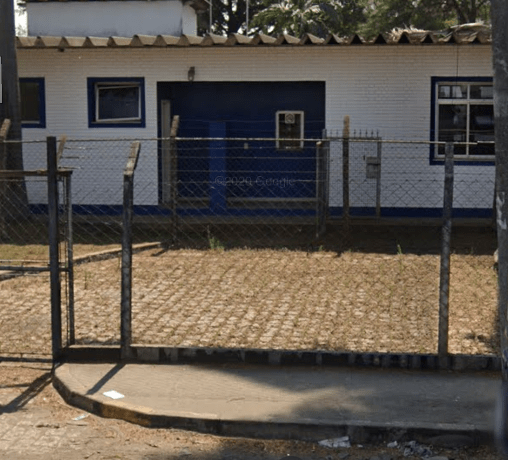
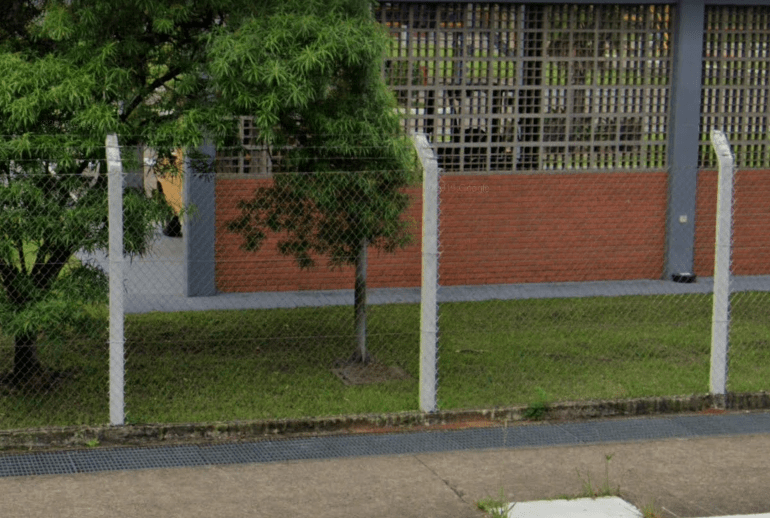
The fences vary from facility to facility (there are over 40 in the country), but bellow there are some pictures of some of them for reference:

I don’t know what extra information I need to define this really, so I would appreciate any guidance you guys can give me. In other words, I’m lost.
thread238-69334 and thread238-432617 were found during my searches and they are close to what I’m soliciting, but most of the comments suggests that some calculations should be performed according to IEEE-80…is this really necessary for something like this? And for something that is related mainly to lightning protection?
By the way, just to clarify why I’m doing such a thing that is very unrelated to my formation: I work as a consultant of R&D for a company, and most of the subjects fall outside my expertise. It is usually not a problem as the “research” aspect is usually linked to standards and whatnot. In this case though, I’m failing to find any palpable resource to define this maximum distance.
Hope you all stay healthy and safe!
Daniel
Rio de Janeiro - Brazil
Now, for the perimeter fences, I’m being told of the need to insert grounding rods every 50m to ground it, on top of electrically sectioning it every 200m. There is no electricity generation in the facility so it is basically to protect human and animal lives from lightning electrifying the fences, I reckon. The fences will not be connected to the existing grounding grids.
I’m not an electric engineer (and honestly, I’m very limited in everything regarding electricity) but my gut feeling tells me the 50m of spacing between grounding rods to be a little conservative. I’m ok with the 200m sectioning though. I’ve tried – and failed – to find any solid reference for the grounding of industrial perimeter fences, in particular this spacing between grounding rods.
NFPA 780 Annex H states 45m/92m if the ground is dry/wet, but this annex is more applicable to rural fences AFAIK. IEEE-80 wasn’t of much help in this particular subject.
The fences vary from facility to facility (there are over 40 in the country), but bellow there are some pictures of some of them for reference:
I don’t know what extra information I need to define this really, so I would appreciate any guidance you guys can give me. In other words, I’m lost.
thread238-69334 and thread238-432617 were found during my searches and they are close to what I’m soliciting, but most of the comments suggests that some calculations should be performed according to IEEE-80…is this really necessary for something like this? And for something that is related mainly to lightning protection?
By the way, just to clarify why I’m doing such a thing that is very unrelated to my formation: I work as a consultant of R&D for a company, and most of the subjects fall outside my expertise. It is usually not a problem as the “research” aspect is usually linked to standards and whatnot. In this case though, I’m failing to find any palpable resource to define this maximum distance.
Hope you all stay healthy and safe!
Daniel
Rio de Janeiro - Brazil