bacon4life
Electrical
- Feb 4, 2004
- 1,527
I recently heard about some arcing that puzzled me and I am hoping someone might have some idea of a plausible explanation for the arcing.
Situation:
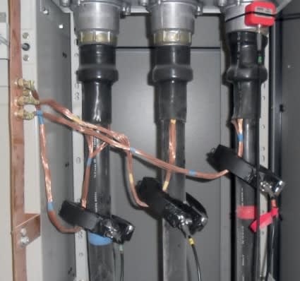
A crew was replacing substation getaway #1, consisting of 150 ft of underground 15 kV cable between the substation switchgear the overhead termination. The installation consisted of three - 350 kcmil 15 kV cables with tape shields plus a bare 4/0 neutral. When the crew touched the 4/0 neutral to the metal beam switchgear enclosure, there was loud and arcing. The arcing continued as the bare conductor was moved across the surface of the beam. I do not know the grounded/isolated status of the opposite end of the cables at the overhead termination. The arcing did not result in significant burning/melting/charring.
The distribution system is wye grounded with a multi-grounded neutral. The substation was in service, with other getaways carrying load when the arcing occurred. The phases on the in- service getaway are somewhat imbalanced, causing flow on the multi-grounded neutral. I am guessing maybe 600 amps of load with 100 amps of neutral current.
Possible explanations include:
1)The imbalance on the in-service getaways was causing flow on the multi-grounded neutral. When the bare copper neutral on getaway #1 contacted the switchgear beam, it formed a parallel path. As the bare conductor moved across the painted surface of the switchgear beam, the path was intermittently interrupted causing arcing. Is there any easy way to estimate likelihood this could generate enough voltage to cause noticeable arcing? A simplistic calculation of voltage resulting from 100 amps flowing through a single cable is 100 amps * 0.256 ohm/1000 ft * 150ft = 4 volts. The system is multi-grounded, so I would expect that only a portion of the imbalance current actually flowed on 4/0 cable installed in the conduit with the 350 kcmil insulated cables.
2)The neutral cable in getaway #1 was energized by induction by sharing a duct bank with other getaways. I assumed not much voltage would be induced by running in parallel for less than 100 ft. I remember doing this sort of calculation by hand in college, but I am hoping someone might have an online calculator I could do quick sanity check.
3)The bare neutral could have picked up capacitive coupling from the overhead 15 kV or distribution line or the 115 kV transmission line. However, the conduit riser going up the pole is vertical, so the cable was mostly perpendicular to the distribution and transmission lines.
4)Anything else?

![[sadeyes] [sadeyes] [sadeyes]](/data/assets/smilies/sadeyes.gif) )
)