Continue to Site

Eng-Tips is the largest engineering community on the Internet

Intelligent Work Forums for Engineering Professionals

  • Congratulations KootK on being selected by the Eng-Tips community for having the most helpful posts in the forums last week. Way to Go!

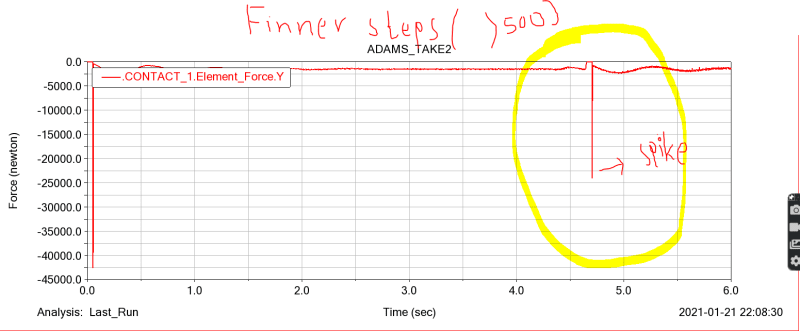
Spike on the graph of reaction force exerted by the ground on the rear wheel at the bump

Status
Not open for further replies.

masterymw

Automotive
Aug 7, 2020
26
Hi,

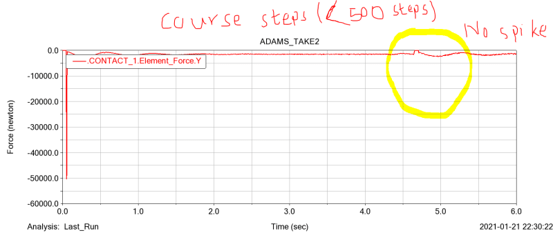
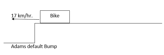
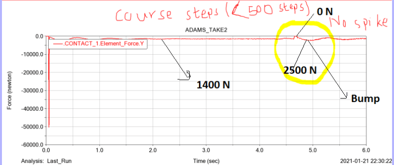
My two wheeler Adams model is subjected to run through the bump of height 10 cm approx. And I am interested in the ground reaction on the rear wheel at the bump when it moves with a velocity 25 km/hr. So I have plotted the ground reaction force on the wheel for a 6-second time span. I have made two graphs with different steps ( 400 steps and 600 steps ). I am pretty confused about which curve should I really trust. The curve of finner steps ( greater than 500) have spikes that show 25 KN ground reaction at the bump while in course one (less than 500 steps), it is smoother than the graph of finner steps ( no spikes at bump ) but of course, It has the effect of bump that shows 2500 N ground reaction force on rear wheel. The ground reaction at rear wheel is 1400 N at rest condition. Any logical suggestion might be helpful for me.

Thanks in advance
errortoask_gkh7ky.png
errortoask2_oe4icz.png
 
Replies continue below

Recommended for you

That is odd. Sadly that's all I can say with the information you've given. I don't understand why a 10 cm bump causes a decrease in force, there again quite why you are using y as the vertical is also a mystery.

Cheers

Greg Locock


New here? Try reading these, they might help FAQ731-376
 
Hi,
I don't understand why a 10 cm bump causes a decrease in force: At rest, the ground reaction on the rear wheel is 1400 N. After moving through the 10 cm bump with a velocity of 25 km/hr, it becomes 2500 N at course steps ( less than 500 steps )which is an increase due to bump but when I simulate the exact model with the same condition at finner steps, the ground reaction becomes 25 KN due to the spike.

there again quite why you are using y as the vertical is also a mystery: I need only the Normal reaction force due to ground on the wheel which is in the y-direction in my model.

Thanks in advance!
 
Contact is generally a very ... fickle thing element. It can show a different value not only depending on the step, but also the type of the selected solver, damping and stiffness settings, and so on. Therefore, personally, I try to use it only to simulate some kind of constraint. In general, according to my personal observations, a smaller step size and stiffness based on 0.1mm penetration under a given weight gives a more or less adequate result.
And by the way, if you have a tire, why not try using the standard "tire" element from the "special forces" tab?
 
Yes, I too agree that there is a lot of variation in the result due to a slight change in different parameters when we use to contact between road profile and wheel tire. More importantly, there is a significant fluctuation in simulating impact fore mainly. I observe it works fine at rest condition. That's why I assume it will work fine at the dynamic condition on impact force too when a bike hits a bump.

As you suggested, It is better to look into a graph of a standard tire from special force rather than the graph of vertical contact force.

Thank you for your valuable suggestion. [dazed]
 
AS shown in the picture above, the red curve is between 5000 N to 0 N. When I put the cursor, it shows 1400 N before the bump. The bump is at the time of 5 seconds which I have circled in the graph. At the time of the bump, the force has become zero because It is a step bump, and the rear wheel is in the air for a very short time (that's why it shows zero force at bump )
bump_os9sey.png
q_lsbb5e.png


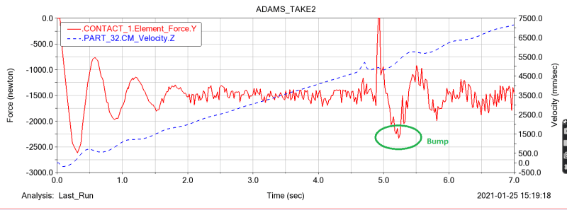
This is the same curve with a closer look.
image_19_flkjzl.png
 
Tire Stiffnes: I have used the wheel model " PAC_MC_120_70R17_cross,tir". In which, Tire vertical stiffness is written as 1.9e+05 N/m and vertical damping is 50 N/(m/s)

Front fork stiffness: 35 N/mm and damping is 1.5 N-s/mm
Rear shock stiffness:78 N/mm and damping is 1.5 N-s/mm

Unsprung mass: rear wheel assembly: 12 kg
front-wheel assembly:10 kg
front fork: 8.8 kg
rear shock: a mass of rear shock isn't taken into account. ( Although I had to assume this mass, I didn't see any mass input dialogue in springs input dialogue )

rear axle : 0.58 kg
front axle 0.46 kg ,
swing arm : 3.5 kg
 
OK, so what I think is happening is that as the rear wheel regains contact with the ground, at the higher simulation speed you are exciting a resonance in the model. Your spring rate, and especially damping, are very high, and your sprung mass is low, I get wheelhop at 18 Hz. I suggest you try a more realistic damping curve in the shock absorbers, unless that is a measured number.

Cheers

Greg Locock


New here? Try reading these, they might help FAQ731-376
 
Status
Not open for further replies.

Part and Inventory Search

Sponsor