Continue to Site

Eng-Tips is the largest engineering community on the Internet

Intelligent Work Forums for Engineering Professionals

  • Congratulations GregLocock on being selected by the Eng-Tips community for having the most helpful posts in the forums last week. Way to Go!

Spline DXF 1

Status
Not open for further replies.

aeromatt

Aerospace
Jun 1, 2005
21
Hello Eng-Tips Community,

I am in need of a dxf of a female JIS spline that will be cut with wire EDM. I attempted to reply to a similar thread but for some reason it was not working. Maybe the thread was so old that it was closed.

Here is what I have for spline specification (see jpg). Please let me know if there is something missing and what I should do to get a dxf or step file created using the provided data.
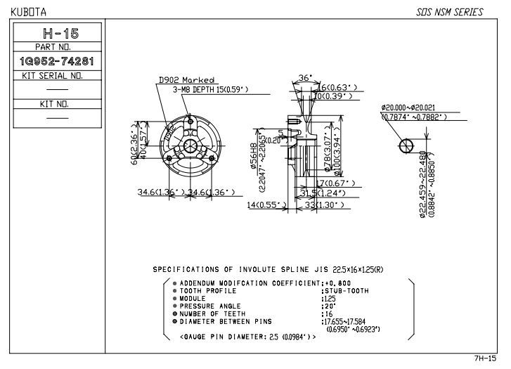
JIS_22.5x16x1.25_R_isikxw.jpg


I welcome any guidance on how to do this and problems that I could run into since I have very little experience with spline manufacturing. The wire EDM shop will require a .005" radius at the inside corners.

Thank you,

Matt
 
Replies continue below

Recommended for you

The spline is as per the JIS-D-2001 standard.
Usually used in automotive applications.
It's the only spline standard that I know of which uses a 20deg generating pressure angle.
Take that drawing to any reputable gear shop and they should be able to help you reproduce the tooth profile in DXF.
Having the mating part will be very helpful.
 
Thanks Gearcutter. Not having a lot of luck finding a gear cutter but I will give it another try.
 
If you don't have any luck, get back to us and we'll see if we can help.
 
Thank you for the replies. Spigor, you are awesome - thanks again!

Matt
 
Can anyone please explain why the max major diameter of the spline is 22.48mm and the spec calls for min diameter between pins (2.5mm each) to be 17.584mm but if you were to actually measure it with 2.5mm pins you would get 17.48mm between pins? Is it assumed that the pins would have a flat to compensate for the discrepancy?
 
The pins do not lay on the major diameter.
They are meant to lay in 180deg opposed tooth-gaps, seating against the flanks somewhere around the theoretical pitch line.
The pins have a small flat ground into them to help ensure that they do not seat on the root/major diameter.

For some reason I'm unable to open spigor's DXF. Make sure there are no radii less than 0.005" on the entire profile. Any smaller and this will cause issues with the wire EDM.
 
Thanks Gearcutter! "root/major" diameter is what I should have said.

Hopefully I have enough info to proceed but I know where to go if not - you guys are great for helping me. Thank you
 
Status
Not open for further replies.

Part and Inventory Search

Sponsor