Eng-Tips is the largest engineering community on the Internet

Intelligent Work Forums for Engineering Professionals

  • Congratulations waross on being selected by the Eng-Tips community for having the most helpful posts in the forums last week. Way to Go!

Sprocket- jackshaft-final lifting capabilities help 3

Status
Not open for further replies.

rjsutton

Mechanical
Aug 1, 2019
12
NZ
Hi
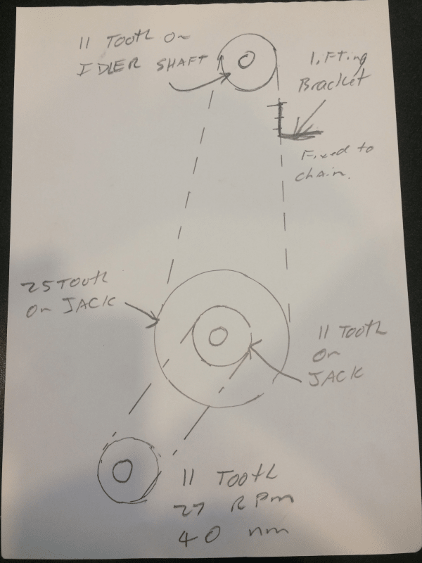
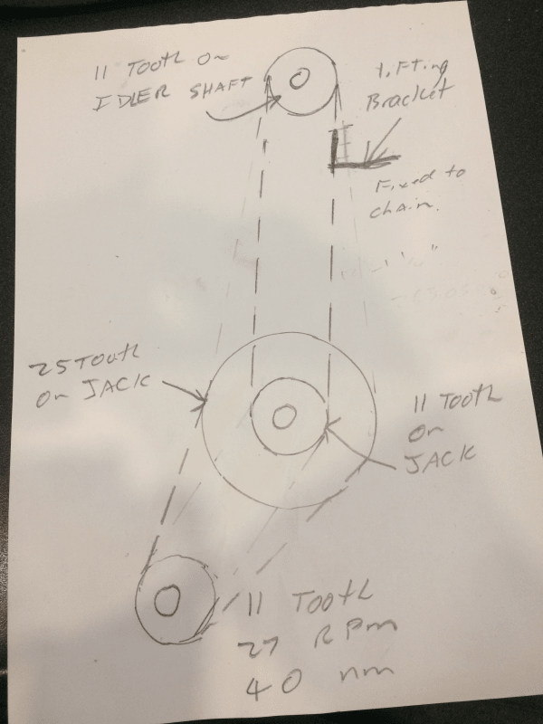
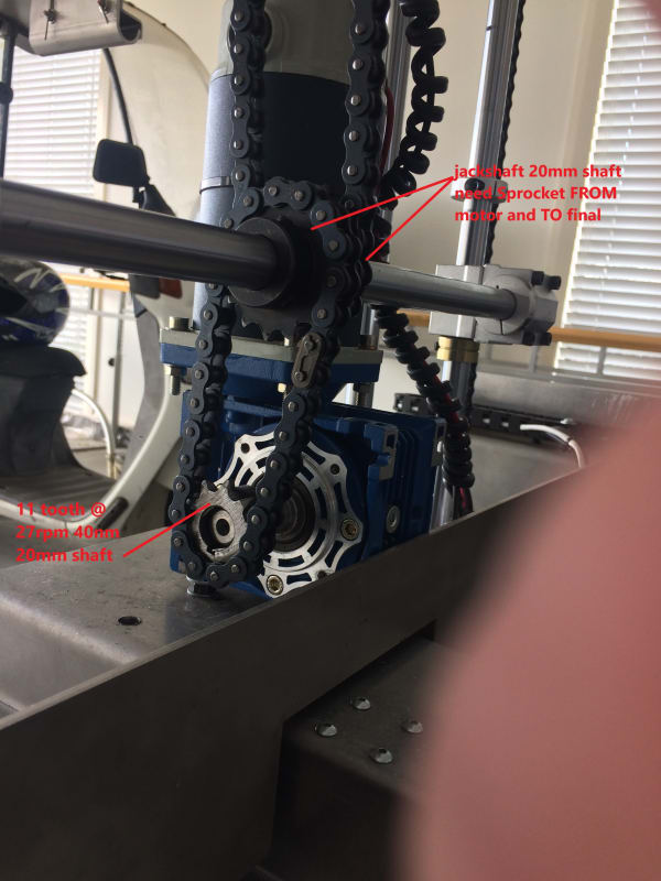
I have a machine in progress where i have a 200W 12vDC motor going thru a reduction box at 1:80 (final speed 27rmp) giving 40N.m ( 400kgf.CM )I am using an 11tooth 428 sprocket to drive a jackshaft off this reduction box.
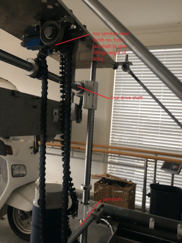
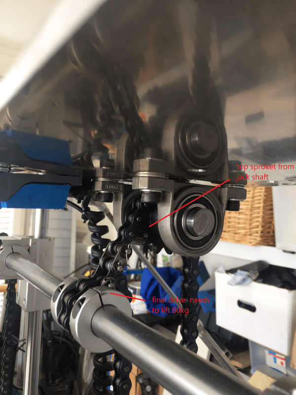
I have a final lifting weight of 80kg which will be lifted by the final shaft. I would really like some help in sorting out what size sprockets i need to reduce the jackshaft speed and final drive to achieve this power. The final SPEED of the shaft is not that important its the lifting capacity i need.The final lifting shaft is attached to the drive chain from the jackshaft to the top sprocket. maybe this configuration is not the right one . do i need a further jackshaft somewhere ? i have a measurement problem where the outside dia of the very TOP sprocket cannot be more than 100mm (25T)
any and all comments and help massively appreciated
thankyou Richard
drive_to_jack_syvvnp.jpg
top_sprocket_final_drive_1_duahhk.png
top_sprocket_final_drive_efhexu.png
top_sprocket-final_drive_pkbzkp.png
 
Replies continue below

Recommended for you

Torque is force times distance (or radius). Similarly Force is torque divided by distance.
Power is torque times angular rate in radians (2*PI radians per 360 degrees)
Power is also force times velocity

With that in mind the power supplied by the motor is all the power available, but by trading off the ratios at the sprockets the force / torque can be changed, neglecting force and power losses due to friction.

You mention that this is 428 chain, which has a pitch of 12.7 mm. Which means that the radius between the center of the gearbox to the chain is defined. Roughly 11 pitches = 11*12.7, which is approximately the circumference of the circle they lie on. radius = circumference/2*pi => (11*12.7)/(2*pi) or about 22 mm. Since it is rigid links the radius the torque is acting on is less than this, but it's close enough for this purpose.

So the 40N-m = 40,000N-mm, divided by 22 mm means the chain can see up to 1818 N.

Assuming the jack shaft has 2 identical sprockets then what comes in is what goes out. If not, the next calculations can be expanded as needed.

If the next sprocket has 25 teeth, then that radius will be (25*12.7)/(2*pi) = 50.5mm radius approximately.

1818N * 50.5mm = about 92,000 N-mm.

If there is another 11 tooth sprocket then the 92,000N-mm divided by the 22 mm means that the tension on that chain can be 4175N

At a typical 9.81m-sec^2 acceleration from gravity, this translates into a lifting ability of (4175N/9.81m-sec^2)kg; about 425 kg as a payload.

Again, the load will be reduced by friction, so additional ratio can be achieved at the first jackshaft (recall assumed that both sprockets were the same there) by putting a pair of different sized sprockets there; say a 12+ sprocket in with an 11 tooth sprocket out.

Note that the speed ratios/ tension ratios can be calculated by just the ratio of the teeth, but that skips calculating the intermediate forces. So if the input chain to a jack shaft has 1000 N of tension and the output has 3000 N of tension, then the shaft has to be sturdy enough to take the 2000 N difference. And the final shaft is going to see the chain pulling down on one side and the load pulling down on the other side, doubling the force applied by the chain.
 
I would add that the pictures show a very flexible/flimsy support structure for the size of the drive components. That is very likely cause a lot of problems.
 
3D Dave
Thanks for your ideas. Im having a blond moment. Are you saying that if i have an 11 tooth on motor output driving a 25 tooth on jackshaft ( this is one complete drive circuit)
NEXT
if i then run an 11 tooth from jackshaft (output) to an 11 tooth at the top ( 2nd drive circuit) and i connect my lifting point on this chain ( as shown in last pic) then this point shout be able to lift 425KG --
I have a funny feeling that i am missing a drive circuit or is the final drive being attached to the 2nd circuit chain ok?
sorry to be vague but have attached a hand drawing of what im thinking is the answer to YOUR comments. Is this correct?
thanks
drive_circuit_glui5d.png
 
Hi Compositepro
Can you expand on your comment
all the circular rails are solid carbon steel linear shafts the main ones are 30mm d and the rest 25mm d These have internal threads connecting them to the top and bottom plates ( 4mm 304 stainless plate)all bolts are grade 12.9
all the shafts are running on SCS linear bearings
Would appreciate your input pleaseas to where you see the weak points
thanks and have a great weekend
Richard
 
Your diagram is of an 11 tooth sprocket driving an 11 tooth sprocket.
 
Your sprockets are mounted on shafts far from the support bearings. "Far" means many times the shaft diameter. The bearings are mounted on thin flat plates. "Thin" means relative to the span of the plate. You have a tie-rod support with a thin, bent strip of metal in the load path. All of this adds-up to flexible. You seem to have little understanding or feel for how shape affects stiffness. C-channels or hollow square shapes can have ten times or more of the flexural stiffness of a flat plate of equivalent weight.
 
Hi Compositepro
i see where you are saying the tie-rods are thin but have nothing to do with the lifting part of the machine and are only stabilizers and yes i agree the plates are thin. This is a prototype and had to add the plates to achieve the tie-rod position.The final the top "plate" will be increased in size to have the holes drilled thru the new top plate ( not suspended). This is 4mm Stainless plate so is incredibly strong. The total width of the plates -rods is 800mm. as above the rods are 30 and 25mm dia carbon steel linear rods and they dont bend-flex at all ( ive tried to bend)
also in final the top plate will have a plate welded under it (50 x 4mm ss ) to supply downward bending protection. Please note this is a Prototype so fixes will be made.
thanks
 
Dave
i thought my diag shows a 11 driving an 11 then a 25 fixed to same jackshaft driving the top 11.
I assume ive got it horribly wrong BUT re reading your initial post i thought i had followed your plan.
is it possible for you to sketch WHAT you actually mean please . As stated the ONLY restriction is the diameter of the TOP sprocket.
Appreciate yours or anyone's drawing
thanks
 
Nope I wrote: 11->(25 joined to 11)->11 is what I suggested. 25 teeth on the input to the intermediate shaft turn 11 teeth on the output, decreasing speed and increasing force.

You have 11->(11 joined to 25)->11, so your diagram is a gear speedup and torque loss method. 11 teeth on the input turn and run 25 teeth on the output increase speed and decrease force.
 
Dave s shown?
if i increase the TOP sprocket from an 11 to say a 15 will that further reduce speed but increase lifting power?
and do you see any problem with the lifting racket being fixed to the chain ( as in last photo ) or should this be run off a different shaft????
thanks again
Richard
revised_s1ljas.png
 
Your most recent sketch is better. Now you have a reduction ratio that will increase force by 25/11 (2.27:1) at the expense of speed. The top idler sprocket does not factor into your lifting force. The sprocket on the motor and the two sprockets on the jack shaft do.

Depending on your lifting needs, you can use something equivalent to an ANSI link that provides a mounting point for other items. Be aware of two things - 1. check the load rating for the link and provide adequate safety factors 2. When lifting directly using the chain, you will create a moment that will want to "bend" the chain (not from the side, but in the same direction as its links. That may or may not be an issue for you but it may induce extra tension in the chain.

Also check with companies like Martin that have extensive documents on chain drive design and sprocket sizing recommendations.

Finally, since you are lifting something, make sure you have plenty of safety factor in your components.

Kyle

 
Kyle
thanks for the confirmation-comments
i have created a LOOP in the chain as shown in pic 4 above. this encircles the lifting bar and works remarkably well.I hope a 428 chain should lift 80kgs with no problem
cheers Richard
 
Status
Not open for further replies.

Part and Inventory Search

Sponsor

Back
Top