Eng-Tips is the largest engineering community on the Internet

Intelligent Work Forums for Engineering Professionals

  • Congratulations waross on being selected by the Tek-Tips community for having the most helpful posts in the forums last week. Way to Go!

Square to round ducting flat pattern with bend lines NX

Status
Not open for further replies.

Paul1342

Mechanical
Nov 18, 2022
3
0
0
ZA
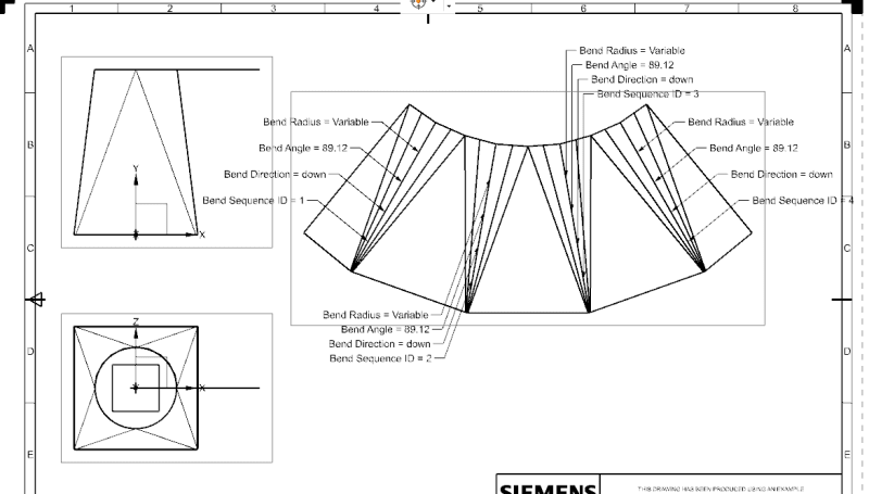
Hello everyone, I would like to make a square-to-round ducting and flat pattern it for laser cutting. The bend lines should originate from the square corners like the picture below done in Solidworks.
Correct_one_from_solidworks_oazwvi.png


- I have used the through curves method, but that method does not show the bend lines in the flat pattern.
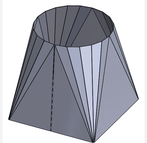
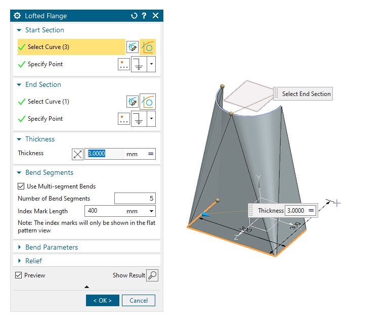
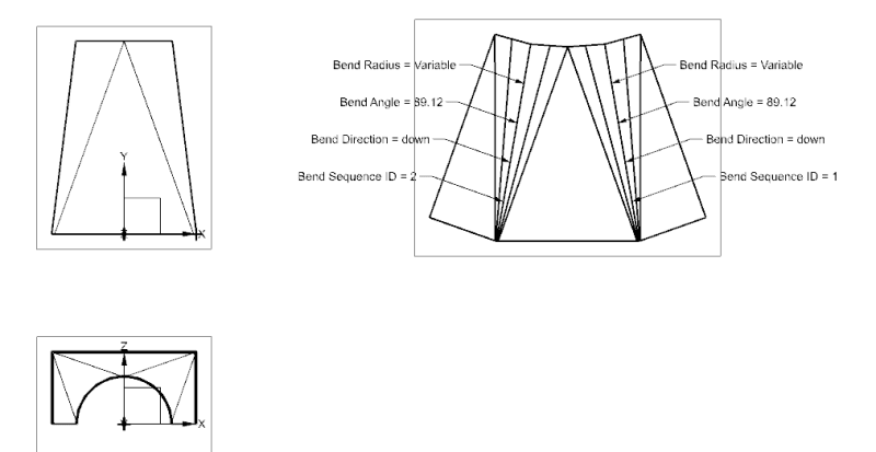
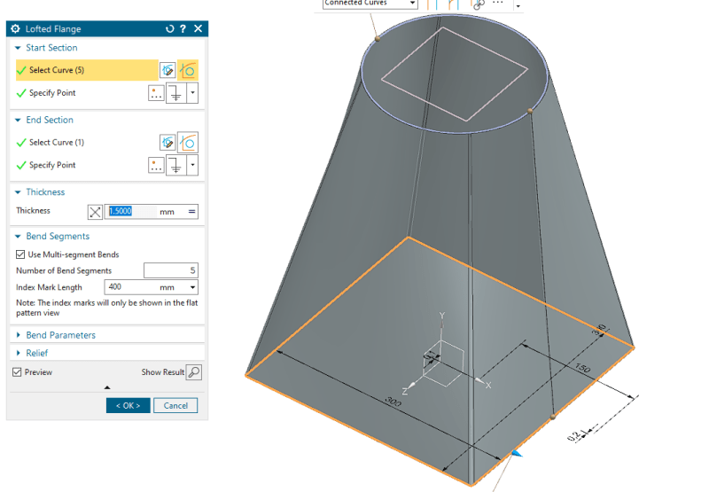
- Then I used the Lofted flange option in sheet metal, where you can set the total bend lines you want in the "bend segments" this method works great, as seen in photo 1 and 2 below.
1_ahjv9z.png
2_hwiqte.png
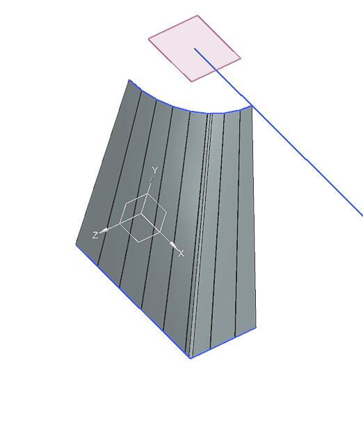
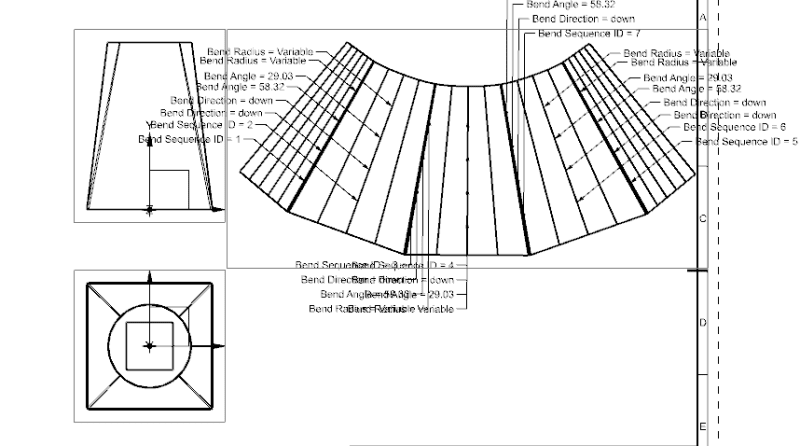
Ths is exactly how I want the ducting to look like. When doing only half of the shape the lofted flange works great, but when doing it for the full shape and making a small cut-out before doing the lofted flange, the shape of the ducting is not what I want, as the bend lines are now everywhere instead of only from the square corners, can be seen below.
4_ocb6nh.png
3_ixzcg5.png


I have been struggling with this for a time now, it is such an irritation because SolidWorks can do this easily.
Any help will be much appreciated
 
Replies continue below

Recommended for you

It's been my observation that Solidworks has often created very special solutions for very typical problems. They do this "easily" because they have faked over some difficulties that get blended away in the manufacturing of the part, like the way that the picture shows a square to polygon, not a square to circle.

Instead of a circle, use 4 arc segments and tiny straight segments to match the arcs and straights on the square base. This should cause the software to match vertex to vertex with straight segment interpolation between them.

Edit: Well then - OK. You fixed it while I was typing.
 
Hi 3DDave, thank you for the help, I have done that, the problem with that is that the bend lines don't originate from the corners
6_tadtnc.png
 
That must be using an approximation curve for the boundary rather than a composite curve - not sure what they call them in NX, but the approximation curve is a spline curve that replaces the underlying segments of a composite curve.

It also looks like this is also a specialized function in NX, where it takes the sharp corner in the square section and creates its own radius, screwing up the matching of segments.

I notice that the choice is "Select Curves" and I suspect you are using the "Connected Curve" option rather than picking individual curves for each part of the loft.

They should have gone all in and just made a square to round a fundamental feature.
 
The sheet metal application is somewhat based upon the fact that sheet metal always has a thickness, you "must" somehow soften a sharp corner. There is a bend radius setting in this menu which will be used.
You can set the bend radius to 0 if you apply the material to the outside.
I doubt that "connected curves" instead of "select curves" would make any difference, not in NX, maybe other systems have or use that trick.
NX is pretty honest in that a "line is a line" and not an approximation. There might be exceptions to this rule?


Regards,
Tomas


The more you know about a subject, the more you know how little you know about that subject.
 
If you do a search in this forum, you should be able to find previous threads that should help you because this topic has been brought up before.

Jerry J.
UGV5-NX1899
 
Status
Not open for further replies.
Back
Top