Continue to Site

Eng-Tips is the largest engineering community on the Internet

Intelligent Work Forums for Engineering Professionals

  • Congratulations pierreick on being selected by the Eng-Tips community for having the most helpful posts in the forums last week. Way to Go!

STAAD: Plate Stress Axes 2

Status
Not open for further replies.

Althalus

Structural
Jan 21, 2003
151
I have a question about the STAAD plate stress axes.

I have a large box culvert that is of unusual dimensions with unusual load conditions.

I've modeled it with plates. At one reentrant corner (the box culvert takes a 90 degree turn) I see a high stress concentration when I place the load near that corner. This is to be expected.

The trouble is that the walls, floor, and roof of the box culvert are all 24" thick. So I'm having trouble figuring out which face that stress is -- and in what direction. The 24" thickness while trying to model with ostensibly thin plates with a "dimension" of 24" makes it difficult to interpret the outpug.

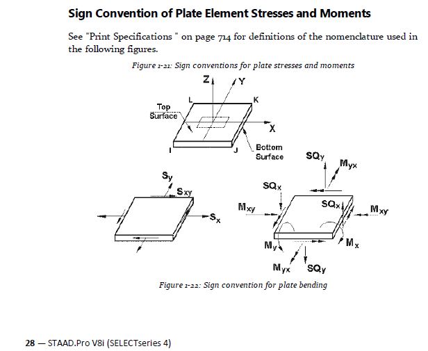
I know that the shear loads I'm looking for are SQX & SQY. But I can't properly interpret which faces/directions the shear loads are actually felt. What exactly are the X and the Y in the "SQX" & "SQY"?
 
Replies continue below

Recommended for you

Have you looked in the Staad technical reference manual? There is a lot of good info in there. Below is a snip from an older version.

I think if you just google "Staad Technical Reference Manual" then you can find it.

Capture_hwelbr.jpg
 
This thread raises the issue of using a computer program without understanding where the numbers come from. How can anyone be confident about such an analysis?
 
Thank you for the responses. Those axes are as I understood them to be. But there is still a problem. The stresses I'm getting seem to be on the wrong axes.

Illustration:
Imagine an integrated slab/wall interface all being modeled as plates.
The x-axis of the roof plates are into the face of wall.
Loads for maximum shear are placed on slab just off of the face of wall.

But the results are weird.

The highest SQx corner stresses (mind you, not SQy) are between the two wall elements (as if it was SQy) not the two slabs, and not between the wall and the slab.

I've looked at all the loads and geometry. It is a very basic load/geometry. But that result simply doesn't make sense

My primary guess is about how the plates are being modeled. Because they are 24" thick, we modeled the roof/wall intersection at the center of plate thickness. So, the top "wall" plate is modeled as a 1' wide horizontal plate supported on the far end with a vertical plate located at the center of wall coordinates.

I've replaced the wall plates with steel members at the face of wall, center of wall, and outside face of wall to see what kind of reactions I'm getting. And they indicate that the shear is the highest near the face of wall as would be expected.

So, why is the plate model showing highest stresses as SQy?

BOTTOM LINE: It appears I understand the stresses and their respective axes correctly. I was just wondering if I was missing something about the directions. So, thank you for your help. I just need to spend more time figuring out my inputs.
 
When checking a STAAD model, I've never paid too much attention to whether it was SQx or SQy. Just checked the shear.

If you are worried about it, have you tried turning on the plate orientation and looking at it that way?
 
Status
Not open for further replies.

Part and Inventory Search

Sponsor