Continue to Site

Eng-Tips is the largest engineering community on the Internet

Intelligent Work Forums for Engineering Professionals

  • Congratulations IDS on being selected by the Eng-Tips community for having the most helpful posts in the forums last week. Way to Go!

Stability Of Simple Supported Beams With An Internal Hinge 5

Status
Not open for further replies.

CaptHope

Structural
Mar 29, 2007
5
Hi dear friends.I was reviewing and remembering very basic concepts of structural analysis course for my MSc entering exam since it had been 16 years after my graduate. While I was solving some problems on stability and determinacy of structures, I encountered a truss problem. While solving that one, I was trying to analyze the configuration of its members to try to figure out its internal stability visually. Then I failed, my answer, which was relied upon try to figure out the movement possibilities of joints using geometrical properties of them, was wrong. And then I started to try to understand what I did/thought wrong. So, at the end, the below problem has arised as a sample of my thinking way during this problem.

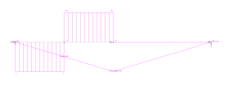
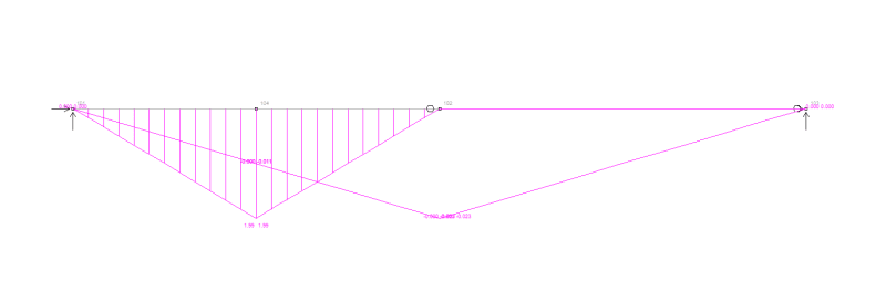
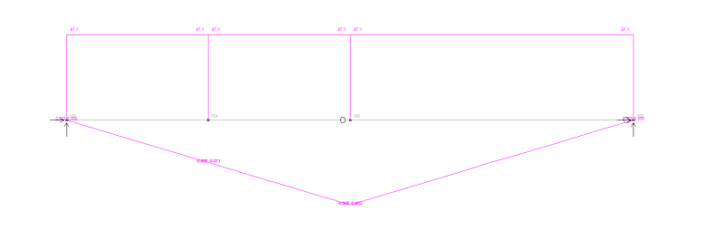
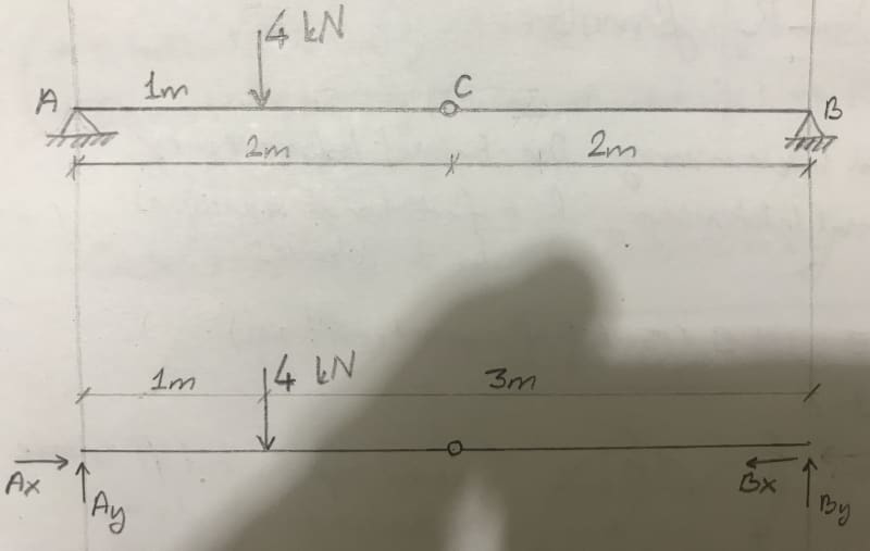
It is a simple supported beam at two ends with an internal hinge.
8A199695-A8BF-4AE7-893C-05208667E843_eraavp.jpg


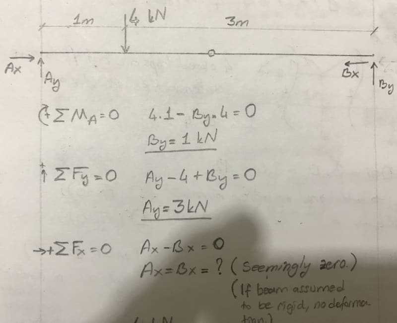
If you write equilibrium equations:
46918C5B-2381-4918-BB17-0401D739ED4C_rync28.jpg


Then, for the section that is cut trough the hinge:
AC833DCE-1E9F-4FC5-A3B9-A2D4BA6021A6_ltob8u.jpg


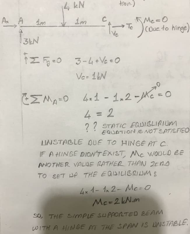
Since the equilibrium can never be satisfied in this way, I say it is not stable.

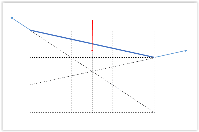
But, the below is another approach using geometry:
6B9F32CD-63ED-452B-BC65-30158231A215_bi9kc3.jpg


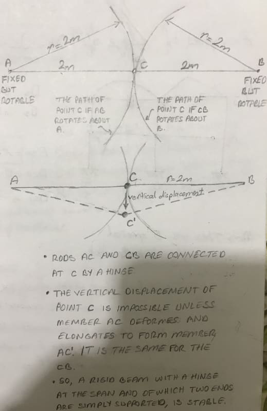
And this time, since it is impossible to move point C downwards without deforming the rods, and since the rods assumed to be rigid, then I conclude that this beam is stable.

My mind is mixed up a bit. But I think I may be overlooking some very basic assumptions about statics, structural analysis, etc.

Can you help me figuring out what I am overlooking or where I am wrong?

Thank you.
 
Replies continue below

Recommended for you

Simple beam theory ignores the effect of longitudinal forces and deflections are assumed to be small enough that their effect on the geometry is negligible.

Neither of those assumptions are valid for a hinged beam pinned at both ends.

To make the model appropriate for simple beam theory one support should be a pinned roller, rather than a fixed pin, and in that case your conclusion that the beam is unstable is correct.

A flexible cable pinned at both ends is stable under vertical loads, so clearly a hinged beam would be as well.


Doug Jenkins
Interactive Design Services
 
I believe your 3kN reaction at A is incorrect, you're thinking about the entire system acting like a continuous beam in determining this 3kN. But it isn't due to the presence of the hinge.

Ignoring the axial issue for a moment if Beam AC is taken out of the system as a free body and is effectively simply supported then shouldn't the A reaction and Vc be 2kN each acting upwards? This satisfies vertical and moment equilibrium for AC portion, I believe this is where your thinking has taken a wrong turn.

Putting Vc on CB causes rotation of system, moving C' down causing axial loads in members as you've recognised. Only member AC carries any bending moment in your system (assuming self weight is negligible).

 
I believe your fundamental conceptual problem is that you are using the assumptions of a 1st order structure and this is a second order structure.

I will just put the load in the middle for simplicity (just replace PL/4 with the required moment at the centre/hinge for a more general case). PL/4=delta*F*cos(theta), P-load at centre, L-full span, F-axial beam load, delta-deflection. calculate delta from the member axial load, E and A. You can solve closed form or do an iterative procedure.
 
This structure is not statically stable. It needs to deflect and go into tension to work.
 
if we make a free body of the beam, the reactions at A and B are fixed (determined) … 3kN at A.

but what about the internal free body ? the internal loads at C ?
well, Ax = Bx (equal and opposite) = Cx
and Cy = 1kN (= By since no other forces on member 2)
so for member 1 we have Ay and Cy reacting the applied 4kN
and we have Ax = Cx (equal and opposite)
but we need to work on moment equilibrium (since C is closer to the load than B, which balances the load correctly).
so assume pt C deflects down, d; now there's a couple Cx*d that's added to sum moments about A …
4*1 = 1*2 + Cx*d.
and we get the same from member 2 …
1*2 = Cx*d
now member 2 is a two force member,
Cx/1 = 2/d
substituting you get 2 = 2 (hooray !)
but now return to member 1, a three force member
and with Ax = Cx = 2/d we can draw the force polygon, with C deflected d …
I think ...


another day in paradise, or is paradise one day closer ?
 
rb1957 said:
so assume pt C deflects down, d; now there's a couple Cx*d that's added to sum moments about A …
Yes, you are right. But then the question arises: So, should we assume this beam as stable(after some deflection-that theoretically it can even be very very small-it comes to rest, however it cannot hold its linear initial form), or unstable( whatever the final outcome is,it shows a movement in the beginning)?

Umit KARAHAN
Civil Engineer
 
I just wanted to add that my reply from the 23rd Sep 2019 is not strictly correct on further reflection. What is correct is that the shear in the member AC is 2kN adjacent to A, I agree due to global equilibrium reaction must be 3kN vertically at A. Therefore the vertical component of the axial load in the rotated member has to be/is 1kN. Noting beam shear is also rotated relative to the support A. So basically what I should have been saying was instead of the reaction being 2kN each end of the member AC, I should have said the beam shear was 2kN at each end of AC member which makes up part of the 3kN reaction at A (the rest coming from the inclined axial load in the member).

This was about as close as I could get the convergence, microstran doesn't really deal that well with non-linear convergence (to the point where I'd say it's basically a waste of time using it for this, but it's all I have available!). But you'll appreciate the effect and interaction of axial load, shear, bending. Obviously axial load developed is dependant on axial stiffness of the chosen member (a 200UC52 in this case), which is a direct function of how much deflection there is, iterate enough and you'll converge to an answer that's pretty close to below.

shear
7_cvqwk1.png

moment
8_j6wuza.png

axial
9_fm1kby.png

vertical reaction at A = 3kN, and at C = 0.997kN (note not fully converged to the expected 1.0kN, but close enough to see what's going on fundamentally).
 
who much does C deflect ?

I wonder if we have to include, in member 1, the fact that C is displaced, that the member isn't horizontal, that the vertical load has a component along the deflected beam ?

Is this a case where deflection (of C) is not small ?


another day in paradise, or is paradise one day closer ?
 
In the example I posted the deflection was 23mm at C, so I believe the effects you're discussing while real, would probably be very small due to very small rotations involved. No more relevant than they would be in a normal simply supported beam undergoing the same degree of deflection I guess. Obviously in practice as well the fixed connections at A and B won't be infinitely stiff.

Basically, while it's interesting as an academic exercise, it's hardly something that might come up in a practical structure. Unless someone can come up for a real world practical use for this type of arrangement?
 
CaptHope said:
So, should we assume this beam as stable(after some deflection-that theoretically it can even be very very small-it comes to rest, however it cannot hold its linear initial form), or unstable( whatever the final outcome is,it shows a movement in the beginning)?

Depends what you mean by "stable".

Is it going to fall down? No.

Is it dodgy? Yes.
 
It is stable. Dodgy is not a defined term.

The structure can be analyzed precisely by considering axial strain in the beam.

BA
 
Agent 66 said:
while it's interesting as an academic exercise, it's hardly something that might come up in a practical structure

I actually designed an art work with vertical cantinary stainless steel rods, springs, and glass work. It was a similar problem but in the end was never built. It will come up once in a life time but I wouldn't hold my breath until another similar project comes along.
 
Practically this is "just" a plastic hinge. Mind you, practically, this'd happen at max bending (where the load is applied); but (practically) maybe something changed in the section locally to locally increase the stresses.

Ok, so if C deflects 25mm, then the horizontal (tension) is 2000/25*1kN = 80kN (from member 2, CB)
then member 1 (AC), sum moments at A … 4kN*1 = 1kN*2+80kN*0.025 … 4 = 4 ...

Screen_Shot_09-24-19_at_07.53_AM_i8y16l.png


thinking about this, 20mm deflection would have an axial reaction of 100kN ? (ie simple statics won't solve)
so you have to bring another constrain to the problem ... either PE from by the load = strain energy in the beam,
or maybe simply strain in member 2 is compatable with deflection.

but how does this answer the stability question ?
the axial tension reduces the static bending moment (looks like max bending is 2kNm) while increasing the tension stress on the section.
does "stability" mean "overload" ?
 
Stability means the structure will not collapse, i.e. it is not a mechanism.

BA
 
what would cause a pinned beam with a single hinge to become a mechanism ?

We seem to be showing that deflection of the beam is limited by the strength of the material.

another day in paradise, or is paradise one day closer ?
 
rb1957 said:
what would cause a pinned beam with a single hinge to become a mechanism ?
A pinned beam with single hinge would become a mechanism if one of the pins becomes a roller or if the hinge becomes a free end.

rb1957 said:
We seem to be showing that deflection of the beam is limited by the strength of the material.
That is true.

Edit: If the strength is adequate, deflection is limited by the strain of the material. If not, the beam fails.
 
"A pinned beam with single hinge would become a mechanism if one of the pins becomes a roller or if the hinge becomes a free end."
so if something breaks so that the supports can no longer react the axial loads ?
if one end is a roller, then the beam cannot develop the required axial loads and would collapse ...
I guess you could call that "instability" or a "mechanism" ... I'd call it "broken".

Aren't "strength" and "strain" interchangeable (due to Hooke's law) ?

another day in paradise, or is paradise one day closer ?
 
Hookes law only covers linear relationships between stress and strain, most materials do not follow this model except at lower strains, for example steel up to yield strain. Aluminium and stainless follow a ramberg osgood relationship that isn't linear at all, etc.

 
Status
Not open for further replies.

Part and Inventory Search

Sponsor