Continue to Site

Eng-Tips is the largest engineering community on the Internet

Intelligent Work Forums for Engineering Professionals

  • Congratulations pierreick on being selected by the Eng-Tips community for having the most helpful posts in the forums last week. Way to Go!

Stability of slender steel beam loaded on bottom flange

Status
Not open for further replies.

molibden

Structural
Apr 11, 2010
200
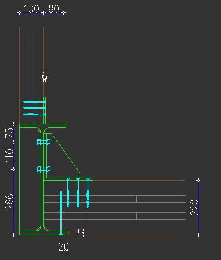
I am curious how would you handle stability issue for this case. I have a 6.4m long beam, height of the beam is 0.45m (IPE450). It is loaded on bottom flange with CLT slabs. In the middle of the span there is quite large point load on top flange from a column above. Beam is simply supported on both ends, lateral support is the same as in span.

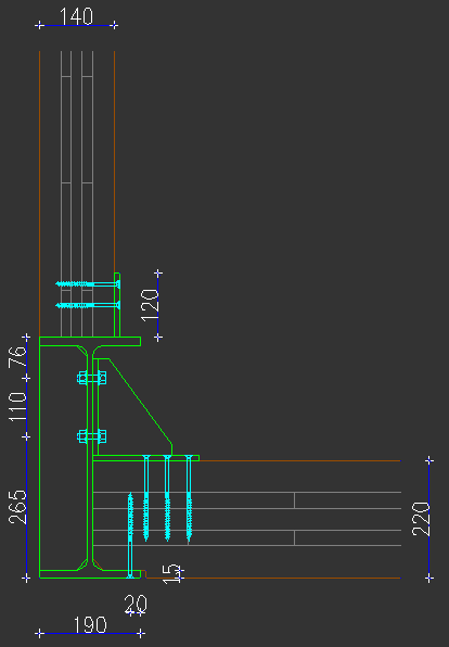
You can see in the detail I provided brackets to connect top portion of the beam with CLT slab. Brackets are spaced 1m O.C. by entire length of the beam. Connection with wall should be neglected as it will not provide lateral stability.

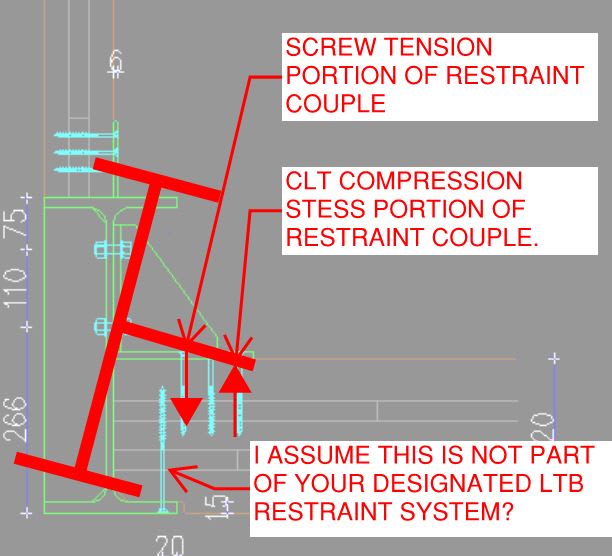
I use Eurocodes but you can give you opinion on it regardless of code. For now I designed the beam as laterally supported and designed the bracket and screws based on lateral force (2% of compression force in the top flange). But I have second thoughts.

ltb_beam_1_tpcamz.png
 
Replies continue below

Recommended for you

Superficial (guestimate) observations (and I won't have time for more for at least 24hrs):

1: The spacing of the restraints seem sufficient for full lateral restraint.
2: The braces seem sufficiently stiff and deep to provide good torsional restraint to the section.
3: The restraining CLT seems sufficiently deep to provide good torsional restraint
4: Lateral restraint on the other ends of the CLT hasn't been mentioned. I presume there is a reasonable load path. But even without it I suspect there is sufficient tonsorial rigidity here to cover you.

At a quick glance I don't see issues. Might be a good idea to consider the extra torsional load given by the eccentric column. The CLT and connections should be fine but worth the check.
 
molibden said:
I am curious how would you handle stability issue for this case.

1) In general, I would do as you have done and attempt to lock the beam rotation to the flexure in the CLT slab.

2) I would like to see a strap and screw arrangement at the bottom of the CLT slab similar to what you show at the top. With that, I'd probably ditch the triangular bracket.

3) If it makes sense to do so, I would attempt to create at least a nominal moment connection between the column and the beam torsion. This may not be theoretically necessary but, when a major, destabilizing load is being delivered in a concentrated fashion, I feel that it's good practice to have some concentrated LTB restraint nearby.

4) Even with the arrangement as you show it, I would approach things a bit different analytically. See the sketch below. I would be treating this set up as torsional bracing rather than transnational. The US steel code has provisions for the strength and stiffness of such bracing schemes.

molibden said:
For now I designed the beam as laterally supported and designed the bracket and screws based on lateral force (2% of compression force in the top flange). But I have second thoughts.

Me too.

5) The 2% business is intended for transnational bracing where as you really have torsional bracing. Perhaps the 2% rule can be modified accordingly but, at the least, I'd think that you'd have to amplify the requirement somehow to account for the lateral resistance being applied at a different level than that of the top flange. You may well have accounted for this already, I'm not sure.

6) It goes largely unsaid but the 2% rule intrinsically assumes that the thing being braced and the thing doing the bracing are of the same material. That's how the rule somewhat gets around having a stiffness requirement when, in reality, brace stiffness is usually more critical than brace strength.

Some questions for you if you can spare the time:

a) Did you intend for your lower screw to be part of the LTB restraint system?

b) What is the magnitude of the uniform load applied to the bottom flange?

c) What is the magnitude of the top flange point load?

d) Is the supported column steel or wood?

e) At what eccentricity is the top flange load coming in relative to the beam centroid?

c01_fkp0v4.jpg
 
molibden said:
I am curious how would you handle stability issue for this case.
...brackets to connect top portion of the beam with CLT slab. Brackets are spaced 1m O.C. by entire length of the beam.

Appears you have selected a reasonable depth beam (span-to-depth ratio of 14:1) and have addressed compression flange lateral bracing at conservative intervals.

I would compare applied moment versus allowable moment for a small sample of unbraced lengths, say 1, 2, and 3 meters. This will provide a subjective idea of how an IPE450 performs under simplified design conditions. If the comparison reveals that the applied moment is relatively "low" in all cases, IMHO, proceed. If not, what to consider next depends on what the these calcs show.

[idea]
 
I agree with all of above with my 2 cents - apply 2% of the total gravity load as horizontal load on top flange of the beam, and sum the resulting torsion within one brace distance, then use it to check the flexural stiffness of the CLT slab. If the resulting capacity exceeds demand, the rotational restraint capability is assured.
 
Thank you all for your comments.

KootK said:
5) The 2% business is intended for transnational bracing where as you really have torsional bracing. Perhaps the 2% rule can be modified accordingly but, at the least, I'd think that you'd have to amplify the requirement somehow to account for the lateral resistance being applied at a different level than that of the top flange. You may well have accounted for this already, I'm not sure.
There is a publication, on page 38, where they state that lateral force is basically just 1,25% Nd if you have more lateral supports. I also added wind force from wall above.

KootK said:
a) Did you intend for your lower screw to be part of the LTB restraint system?
Yes, I assume the point of rotation is at the bottom flange. I have screws 8x160mm @ 250mm along the entire beam. Distance from the edge of CLT is big enough to develop full shear capacity. It is highly unlikely top flange will rotate towards inside. It will rotate outside. I designed the triangular bracket with screws for this case.

KootK said:
b) What is the magnitude of the uniform load applied to the bottom flange?
Design uniform load is approx. 30kN/m.

KootK said:
c) What is the magnitude of the top flange point load?
Design point load is 140kN.

KootK said:
d) Is the supported column steel or wood?
CLT wall, 0.5m long. I have the triangular bracket directly under this wall.

ltb_beam_2_q6aerv.png


KootK said:
e) At what eccentricity is the top flange load coming in relative to the beam centroid?

e=25mm

I also have stiffeners at each bracket location, but only on one side as it is not practical to have them on same side as CLT panels.
 
human909 said:
4: Lateral restraint on the other ends of the CLT hasn't been mentioned.
It is a CLT diaphragm with many shear walls. But as you can presume, this side of the house is fairly open :)

I will try that, good advice.

 
That all sounds pretty great molibden.

molibden said:
There is a publication, on page 38, where they state that lateral force is basically just 1,25% Nd if you have more lateral supports.

That assumes that the brace resisting force is provided at the level of the flange. So, at the level of the top of the slab and assuming rotation about the underside of the slab, you'd use a shear force in your bolt group of about 2.5%, right? You may well have already done this, I'm not sure.
 
Yes, KootK, I have done this way. Now, I'm not sure about screws at bottom flange. How would you calculate force there? Should be the same as for the bracket, right?
 
molibden said:
Now, I'm not sure about screws at bottom flange. How would you calculate force there? Should be the same as for the bracket, right?

For that, I think that you need to consider the top flange rotating to the interior about the top face of the CLT as I showed in my sketch. I'd think that 1.25% would be fine there based on the lever arm. My gut feel is that your screws at 250 o/c should be fine.
 
I'm not sure about screws at bottom flange

Calculate shear flow demand between the slab and bottom flange of the beam, VQ/I.
 
retired13 said:
Calculate shear flow demand between the slab and bottom flange of the beam, VQ/I.
I'm not really having a composite section. Why would you calculate shear flow? Am I missing something?
 
Status
Not open for further replies.

Part and Inventory Search

Sponsor